M20V SERVICE AND MAINTENANCE MANUAL
MOONEY INTERNATIONAL CORPORATION
Date
MAR 2017
Rev Date
Page
5
80-00-00 - GENERAL
The airplane is equipped with a 24 volt starter supplied
with engine package. The starter is located on engine
case at rear of engine.
When ignition switch is placed in “START” position, cur-
rent is supplied through main bus to energize starter
solenoid which in turn connects battery to starter.
80-00-01 - TROUBLESHOOTING
1.
Refer to Section 24-39-04.
80-00-02 - MAINTENANCE
1. Inspect and service starter per Continental Motors
Starter Motor Service Manual. (CMI Aircraft Products,
PO Box 90, Mobile, AL 36601, Attn: Publications De-
partment.)
2. Lubrication - No lubrication is required on starter
motor except at overhaul.
-CAUTION-
Do not clean starter in any degreasing tank or
grease dissolving solvents. Avoid excessive
lubrication. Use only kerosene or Varsol.
80-00-03 - REMOVAL
1. Remove upper and lower cowling (See Chapter
71-10-00).
2. Disconnect electrical wiring from starter termi-
nals.(ref. Fig. 80- 1 and Fig. 80- 2)
3. Remove nut and washer from studs on adapter
mounting pad.
4. Remove starter and O- ring from adapter.
ELECTRICAL
TERMINAL
STARTER
MOTOR
STARTER MOTOR (TYP.)
FIGURE 80- 1
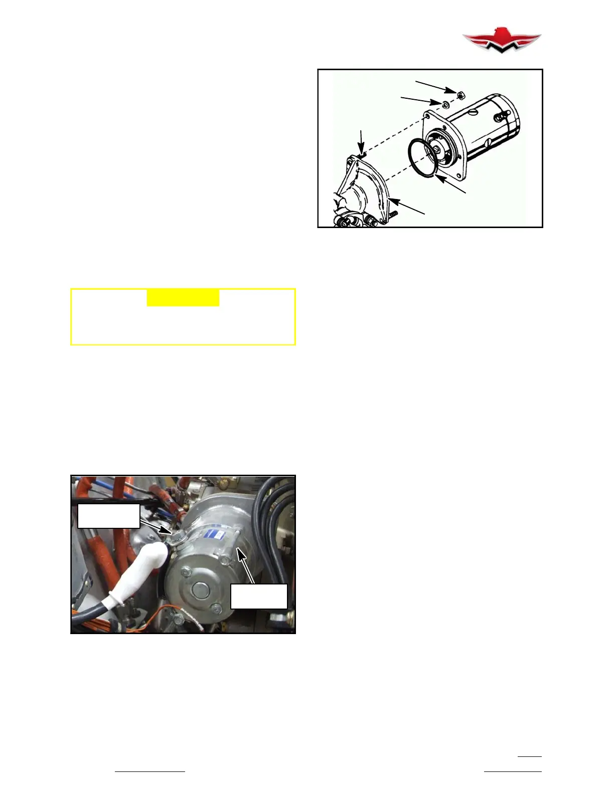
O-RING
WASHER
NUT
MOUNTING PAD
MOUNTING PAD
STUDS
STARTER MOTOR MOUNTING (TYP.)
FIGURE 80- 2
80-00-04 - INSTALLATION
1. Before installation, clean any rust corrosion or dirt
from mounting surface of starter motor.
2. Check all ground straps connections for tightness.
3. Install new O- ring on starter flange.
4. Position starter on mounting pad.
5. Install attaching nuts and washers.
6. Torque nuts 220.0 to 260.0 inch lbs.
7. Connect electrical wiring to starter terminals.
8. Check starter mounting flange for oil leakage be-
fore cowling is installed.
9. Install cowling.
80-00-05 - BRUSHES
Starter brushes should slide freely in holder and make
full contact on commutator. Brushes should be re-
placed when they have worn to .39 or 25/64 of an inch in
length. Brush tension should be 32 to 40 ounces as
measured with spring scale hooked under brush spring
and pulled in straight line opposite force exerted by
spring. Read tension just as spring leaves brush. Refer
to Continental Motors Starter Motor Service Manual for
replacement procedures.
80-10-00 - CRANKING
The starter relay (ref. Fig. 80- 3) is located on the left
side of firewall. The solenoid is energized by placing
ignition/magneto switch in “START” position. Battery
current is then directed to starter. The aircraft are
equipped with a “START POWER” annunciation. This
light illuminates “RED” when starter switch is in start
position or when starter switch or starter solenoid has
malfunctioned and starter is engaged while engine is
running. This malfunction should be corrected before
engine is started again.
80-00-00
 Loading...


