MOONEY INTERNATIONAL CORPORATION
M20V SERVICE & MAINTENANCE MANUAL
Date
MAR 2017
Rev Date
Page
5
91- 00- 00 - GENERAL
The electrical system hardware lists and related schematics are sequenced in this section by serial number effectiv-
ity. The chapter is divided into the following sections:
- Electrical Systems Schematic Notes
- Wiring Identification System
- Electrical System Hardware Charts (By Effectivity)
- Electrical Schematics (By Effectivity)
91- 00- 01 - ELECTRICAL SYSTEMS SCHEMATICS NOTES
1. All electrical wiring, assemblies, and installations
must be in accord with FAR 43 and AC 43.13- 1( ).
2. All splices must be “AMP” disconnect or equiva-
lent.
3. All circuit breakers are trip- free.
4. All terminals are Spec. MS25036 (or equivalent or
they must be soldered).
5. All terminals must be preinsulated or must be insu-
lated with “Ampsulation” (or equivalent).
6. Wires without dash numbers are furnished by the
manufacturer and are included with the equipment.
7. The symbol “
” indicates a knife discon-
nect.
8. Optional equipment may be installed as required.
9. Wires denoted by === === === symbols to be
twisted counter clockwise with a minimum of three (3)
wraps per foot.
10. “F” denotes ground through frame (no wires).
11. All knife disconnect splices to be insulated with
PVC105 and securely string tied with Airtex no. 417
cord.
12. All wire sizes are minimum sizes acceptable.
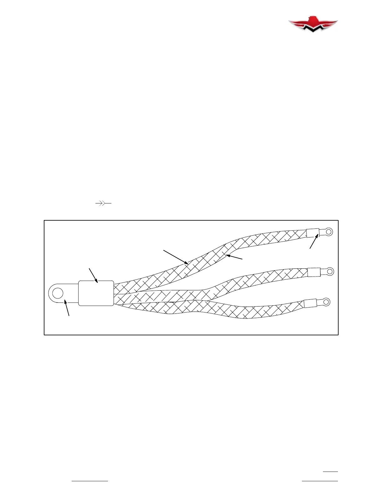
13. Use 913127 buss bars as necessary for various
configuration changes and manufacture interconnect-
ing buss using no. 2170 tubular braid covered with
PVC105/5/16” (both Alpha Wire Co.) and terminated
with AMP terminals of appropriate sizes.
321298 TERMINAL
327218 AMPSULATION
PVC 105/ 5/16”
35108 TERMINAL
2170 TUBULAR
BRAID
R91- 1
INTERCONNECTING BUSS EXAMPLE
FIGURE 91- 1
91- 00- 02 - WIRING IDENTIFICATION SYSTEM
The Mooney Aircraft Corporation wiring/equipments identification system used in current production aircraft deletes
the Model Number annotation. The purpose of this is to standardize the identification of a system function/compo-
nent for all model of aircraft. The functional groups are basically the same as earlier identification numbers.
These new functional groups apply to schematic drawing 800416. The new functional groups are as follows:
CR - First two/three letters - Circuit Function
04 - First set of numerals - Wire Sequence
A - Single letter in series - Configuration
20 - Last two numerals in series - Wire Size
91- 00- 00
 Loading...


