MOONEY INTERNATIONAL CORPORATION
M20V SERVICE AND MAINTENANCE MANUAL
Page
Date
5
MAR 2017
Rev Date
8-00-00 - LEVELING
Place a spirit level on the leveling screws above the tail-
cone access door (see Figure 8- 2) when leveling the
aircraft longitudinally. Level the aircraft by increasing or
decreasing air pressure in the nose wheel tire. Level
aircraft laterally by placing level across center seat
tracks forward of wing spar. Front seats must be in the
full forward position when weighing.
8-00-01 - WEIGHT AND BALANCE
To weigh aircraft, select a level and draft free work area,
then:
1. Check for installation of all equipment as listed in
the Weight and Balance Record, Section VI of POH/
AFM.
2. Charlie Weight Installation. The aircraft, as delivered
from the factory, has correct ballast added (if any) to
compensate for installed equipment. If addition or dele-
tion of equipment, at a future time, affect the weight and
balance of the aircraft sufficiently to require a ballast
change, the proper Charlie Weight Installation shown
on Figure 8- 1 is to be used.
-NOTE-
See Section VI of Pilot’s Operating Handbook for
Weight and Balance reference data.
3. Ground aircraft and drain fuel tanks per Section
12-10-02.
4. Add unusable fuel to each tank, (see Pilot’s Oper-
ating Handbook for proper quantity of unusable fuel).
5. Fill oil to capacity (8 quarts).
6. Position a 2000- pound capacity scale under each
of the three wheels.
7. Level aircraft as described in Section 8-00-00 and
center nose wheel.
8. Weigh the aircraft.
9. Find reference point by dropping a plumb- bob
from center of nose gear trunnion (retracting pivot axis)
to floor. Mark point of intersection on floor. Reference
Figure 8- 2.
10. Locate longitudinal centerline of nose wheel axle
and main wheel axles in the same manner. Mark these
points on floor.
11. Measure horizontal distance from the reference
point to main wheel axle center line (Lm/r).
12. Measure horizontal distance from center line of
nose wheel axle to center line of main wheel axles (Lm/
n).
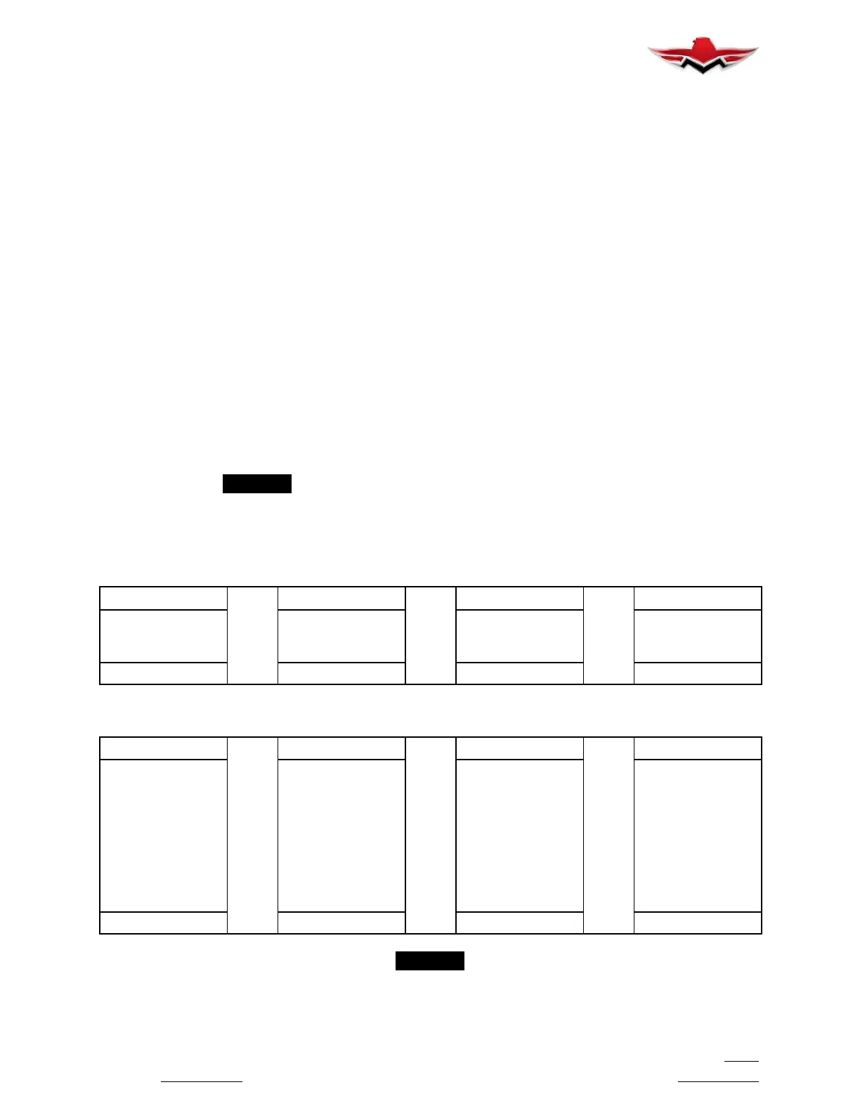
13. Record weights and measurements and com-
pute the basic weight and CG as follows:
a. CG Forward of Main Wheels
LBS.
×
IN.
÷
LBS.
=
IN.
Weight @ Nose
Distance Between
Main & Nose Wheel
Axle Centers
Total Weight of
Aircraft
CG Forward of
Main Wheels
(W
N
) (L
M/N
) (W
T
) (L
M
)
b. CG Aft of Datum (Station 0)
IN.
−
13 IN.
−
IN.
=
IN.
Distance from Cen-
ter
Nose Gear Trunnion
to
Center of Main
Wheel
Axles (Horizontal)
Distance from Nose
Gear Trunnion to
Datum
Result of Computa-
tion
Above (a.)
CG (FUS STA)
DistanceAftofDa-
tum (Empty Weight
CG)
(L
M/R
) (CONSTANT) (L
M
) (L
C/G
)
-NOTE-
Empty weight includes unusable fuel and full oil (8 Qts.) and is computed with gear down and flaps up.
8-00-00
 Loading...


