RIY
The Interface Solution Experts
9
DECADE
RESISTANCE
BOX
RIY
1
2
3
4
+PS
–PS
250
+
–
DC VOLTMETER
12-42 VDC
POWER
SOURCE
+
–
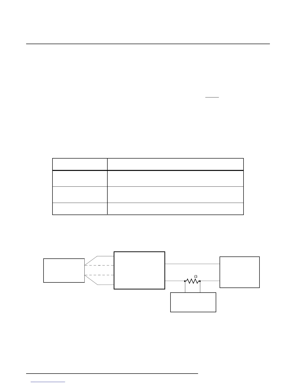
NOTES:
1. Terminals 1 and 4 are the primary connection terminals.
2. To simulate a 3-wire input, use terminal 3 for lead length
compensation
3. To simulate a 4-wire input, use terminals 2 and 3 for lead
length compensation.
(SEE NOTES)
Figure 4 illustrates the calibration setup required to
perform standard ranging.
To monitor the output, a dc voltmeter and a precision
load resistor are called for. Volmeter readings of 1-5
Vdc read across a 250 ohm resistor represent 4-20
mA, proportionally. An output reading of 3 Vdc is
equal to a 12 mA output with a 250 Ohm resistor.
Similar calculations can be made over the 1-5 Vdc
range with the following conversion formula: V
(voltage reading)/250Ω = mA.
Table 3. RIY Calibration Equipment (Standard Ranging)
Equipment
Decade Resistance
Box
Voltmeter and
Precision Resistor
DC Power Source
Specifications
Accuracy of ±0.01%, or better
Digital voltmeter, accuracy of ±0.005% or better; 250Ω precision
resistor, tolerance of ±0.01%
12-42 Vdc
Standard Ranging Procedure
1. Set range and other configuration switches for the
required RTD or ohms input, as necessary (refer
to figure 2 and table 2).
NOTE
Switch SW301-5 must be set to the ‘off’
position to perform standard ranging,
and set switch SW301-6 to the ‘off’
position for units with this switch
functional for keyboard enable.
Figure 4. Calibration Hookup Diagram (Standard Ranging)