RIY
20
The Interface Solution Experts
RIY Quick Reference Sheet
Table A1. SW301 Switch Settings
Settings
ON
OFF
-2 OFF/-3 OFF
-2 OFF/-3 ON
-2 ON/-3 ANY
ON
OFF
ON
OFF
ON
OFF
SW301
-1
-2 & -3
-4
-5
-6
Features
Displays Celsius
Displays Fahrenheit
2-wire, Dual 2-wire
3-wire, Dual 3-wire
4-wire, Triple 2-wire
Downscale Drive
Upscale Drive
Quick Ranging
Standard Ranging
Keyboard Lockout
Keyboard Enable
NOTE: SW301-6 is not active on all units.
Table A2. SW302 Switch Settings
Code
P1
P2
P3
P4
P5
EL1 (or P6)
L4 or P7
L3 or P8
L2 or P9
L1 or P10
EL1 or P11
EL2 or P12
EL3 or P13
Problem
Failed RAM test on power up
Failed ROM checksum on power up
Failed EEPROM checksum on power up
EEPROM did not write properly
EEPROM RTD table is bad
Lead # 1 or 4 is open (2-wire sensor)
Lead #4 is open
Lead #3 is open
Lead #2 is open
Lead #1 is open
RTD/Element #1 is open
RTD/Element #2 is open
RTD/Element #3 is open
Table A3. LCD Displayed Problem Codes
Input Type
Pt 100Ω, 385 RTD
Pt 100Ω, 3923 RTD
Pt 100Ω, 3916 RTD
Pt 100Ω, 3902 RTD
Pt 200Ω, 385 RTD
Pt 500Ω, 385 RTD
Pt 1000Ω, 385 RTD
Pt 1000Ω, 375 RTD
2 or 3 Pt 100Ω, 385 RTD’s (Ave.)
2 Pt 100Ω, 3923 RTD’s (Diff.)
2 Pt 100Ω, 385 RTD’s (Diff.)
2 Pt 500Ω, 385 RTD’s (Diff.)
NI 120Ω RTD
CU 10Ω RTD
Ohms
FLEX-SOR
TM
Input Code
R0
R1
R2
R3
R4
R5
R6
R7
R8
R9
R10
R11
R12
R13
R14
R15
SW302
0
1
2
3
4
5
6
7
8
9
A
B
C
D
E
F
NOTE: For expanded switch setting information refer to the Calibration Section of the RIY User’s
Manual. For expanded hookup information refer to the Installation Section. For expanded
problem code information refer to the Operation Section.
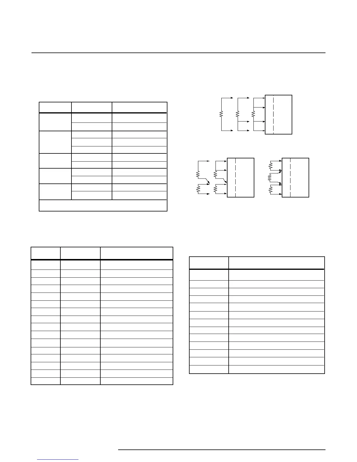
Figure A1. Sensor Hookups
Appendix A
1
2
3
4
SINGLE-SENSOR
HOOKUPS
DUAL-SENSOR
HOOKUPS
TRIPLE-SENSOR
HOOKUP
RIY
1
2
3
4
RIY
1
2
3
4
RIY
RIY
Page 20