Do you have a question about the Moore Industries SPA HLPRG and is the answer not in the manual?
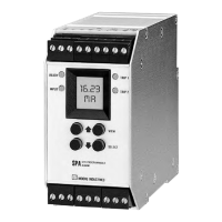
Use VIEW and SELECT buttons for menu scrolling and selection.
Visual guide to SPA setup steps from input selection to alarm configuration.
Details handling of current/voltage inputs and transmitter excitation.
Describes the optional scaleable analog output (0-20mA or 0-5V).
Explains Linear and Custom modes for display scaling and units.
Configuration of up to four contact closure alarms with various parameters.
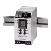
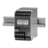
Details DIN case compatibility with G-type and Top-Hat rails.
Lists repeatability, accuracy, stability, deadband, and response times.
Details input impedance, over-range protection, and analog output performance.
Specifies operating/storage ranges, humidity, and RFI/EMI protection.
Outlines front panel controls, internal settings, LCD, and status LEDs.
Defines alarm trigger and return levels, and hysteresis.
Differentiates alarm types and reset behavior.
Explains relay behavior in alarm/non-alarm states based on failsafe setting.
Clarifies "Normal" state for Normally Open/Closed relay contacts.
How to configure relay behavior using internal DIP switches.
Enabling/disabling password protection via jumper.
Setting for current source/sink or voltage output (AO option).
Overview of accessing menus and viewing/changing parameters using front buttons.
Procedure to choose between current (mA) or voltage (V) input.
Setting Linear or Custom mode and engineering units.
Covers "Smart Scaling" and "Bench Scaling" for input calibration.
Procedures for display scaling and AO scaling.
Setting up custom 20-point linearization in Custom Mode.
Setting trip points, deadbands, delays, and alarm types.
Procedure for modifying or checking the unit's password.
Step-by-step guide to inputting the security password.
Accessing menus for viewing without making changes.
Procedure to select between mA and V input types.
How to proceed to the next setup menu or exit.
Explains simple input meter vs. independent scaling capabilities.
Procedure for selecting display units like °C, °F, %, or custom labels.
Option to enable or disable linearization for custom units.
Using the menu to define zero/full scale values without calibration.
Aborting the process or completing it to move to the next menu.
Required connections and warm-up time for calibration.
Using the menu to capture input levels with calibration equipment.
Adjusting the decimal point placement for the display.
Defining the zero and full scale values for the display.
Defining up to 20 points for a custom linearization curve.
Constraints on input (X) and display (Y) values for curve points.
Steps needed before programming linearization (input/display scaling).
Setting zero and full scale values for the analog output signal.
Fine-tuning the zero and full scale analog output using a meter.
Defining the input values that trigger an alarm.
Defining the hysteresis range around the trip point.
Configuring the time delay before an alarm state change.
Selecting whether an alarm trips on high or low input levels.
Configuring how alarms reset after being tripped.
Details valid password range (00-99) and access conditions.
Procedure for setting a new password using the front panel.
Describes the housing and its mounting compatibility.
Details how to mount on Top Hat and G-type DIN-rails.
Provides physical dimensions for dual- and triple/quad-alarm SPAs.
Illustrates wiring for voltage and current inputs.
Detailed breakdown of terminal functions for various SPA configurations.
Guidelines for grounding metal cases, shields, and twisted pairs.
Advice on suppressing voltage spikes from inductive loads.
How the SPA functions based on settings and power-up.
Explains the meaning of READY, INPUT, and TRIP LEDs.
How to use MR terminals for latching alarms.
Lists error messages, their meanings, and recommended actions.
Information for obtaining technical assistance from Moore Industries.
Steps for requesting an RMA and shipping equipment for repair.
Details on warranty status, repair costs, and disclaimers.
| Brand | Moore Industries |
|---|---|
| Model | SPA HLPRG |
| Category | Security System |
| Language | English |