EasyManua.ls Logo

Moore Industries SPA TPRG User Manual

Moore Industries SPA TPRG
32 pages
To Next Page IconTo Next Page
Page #1 background imageLoading...
Page #1 background image
The Interface Solution Experts 1
SPA
SPA
April 2016
224-721-00D
Site-Programmable RTD &
Thermocouple Limit Alarm Trips
Site-Programmable RTD &
Thermocouple Limit Alarm Trips
TPRG
Question and Answer IconNeed help?

Do you have a question about the Moore Industries SPA TPRG and is the answer not in the manual?

Moore Industries SPA TPRG Specifications

General IconGeneral
Communication ProtocolHART
InputRTD, Thermocouple, mA, V, mV, Potentiometer
Output4-20 mA
HousingDIN Rail Mount
Operating Temperature-40 to +85°C (-40 to +185°F)

Summary

SPA Overview and Features

Temperature Input Overview

Overview of the SPA's temperature input capabilities and application.

Input Types

Details on inputs like RTDs, thermocouples, resistance, and millivolt sources.

Output Options

Information on analog output options for current or voltage signals.

Display Functionality

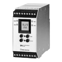
How the SPA display shows input values in °C or °F.

Alarm Configuration

Configuration options for up to four programmable alarm relays.

Sensor Diagnostics Feature

Patented feature for monitoring sensor and wiring status.

Mounting Options

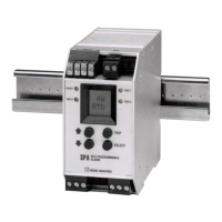
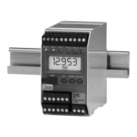
Details on universal mounting options for the SPA on DIN-rails.

Specifications

Alarm Terminology

Internal Settings

TPRG SPA Programming

Main Menu Navigation

Overview of the first level of menus for configuring the SPA.

Password Management

Configure Sensor

Configuration Options

Sensor Failure Handling

How the SPA functions during sensor failure based on installed options.

Alarm Setup

Enter Trip Point (Smart Ranging)

Setting trip points using the Smart Ranging feature.

Input Trip Point (Standard Ranging)

Capturing trip points using an external signal source.

Alarm Trip Point Setup Steps

Enter Deadband

Setting the deadband for alarm trip points.

Enter Delay

Setting the alarm response delay from 0 to 60 seconds.

Alarm Setup Details

Set High/Low Alarm Function

Configuring alarms as high or low trip points.

Set Latching/Non-Latching

Setting alarm latching or non-latching behavior.

Change the Security Password Code

Configure Zero and Full Scale — Smart Ranging

Input Zero and Full Scale — Bench Ranging

Trim Output

Unit Installation

Mounting Procedures

Procedures for mounting the SPA on DIN-rails.

Connections

Indicators and Reset

Front Panel LEDs

Description of front panel LEDs for status indication.

Manual Reset Function

How to perform a manual reset for latching alarms.

Error Codes

Return Procedures

Related product manuals