Conliguring the MPI-712a
to accept Positive
Inputs
The MPI-712a is
pre-conllgured
to accept negative
trigger inputs forlhe Ready
and Armed
LEDs and the
piezo
sounder.
Many
security conkols arq
supplisd
with
positive
outputs.
ll
positive
trigger is requi.ed,
four
taces on the back
ol the
ci.cuit board must
be cut and a
proglamming
change must be made.
tr Circuit
Board Modlflclllon lor Positive
Trigg€r
Inputr
'L
Remove all
power
trom the control staiion.
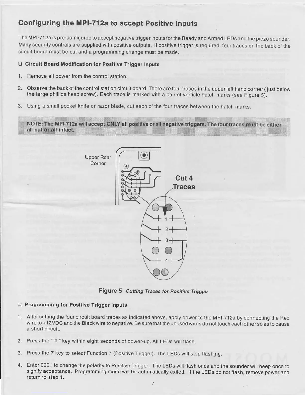
2. Observe
lhe back ol lho conlrol station circuil
board. Th€re are lour kaces
in the
uppet lelt hand corner
(
just
below
the larg6
phillips
head screw). Each trace is marked
wilh a
pair
of vertiole
hatch marks
(see
Figure
5).
3. Using a small
pockel
knife or razor blade,
cut each ol lh6 tour traces
between lhe
halch marks.
UppEr Rear
Corner
Figute
5 Cuting
Tncos tor
positive
frigger
O Progr.mming
for Po!ltlvc
Trlgg€r Inputs
1 . Atter
cutting
the
lour circuit board
traces
as indicated
above, apply
power
to
the Mpl-712a
by
connecting the
Red
wire to
+12VDC
and the Black wire
lo
negalive.
Be sure lhai
the unused wir€s
do nol louch each other
so as lo cause
a short
circuil.
2.
Press the
"
#'
key
wilhin eight seconds
ol
power-up,
All LEos
wilt
lash.
3. Press the
7
key
to
select
Function 7
(Positive
Trigg€r).
The LEDS wi
stop flashing.
4. Enler
0001 to change
the
polarity
io Positive
Trigger.
The LEDS will llash
once and th€
sounder wilt beep once
to
signity
acceptance.
Programmlng mode
wall be automatically
exited. lf
the LEDs do
not llash, remove
power
and
r€turn
to slep ,.
,
Cut 4
'1.1
'31
@
4J
@