2
- INTRODUCTION
Pellet stoves are heat generators suitable for heating a carrier fluid, wa-
ter or air. Moretti Design stoves must be installed according to standard
regulations. All electrical connections and the connection to the chimney
flue must be performed in a proper manner. The aim of this manual is
that to guide the technician during the installation phase, first ignition and
ordinary and extraordinary maintenance of the stove.
The Technician must always have at hand the Technical Manual
together with the Parameters Manual.
THE GOAL OF THE TECHNICIAN
The technician must inform the customer as well as the manufacturer of
all necessary information regarding the product for a proper use and
function. In other words the technician must explain, during the installa-
tion and testing phase of the product, how to properly use the appliance
and in case of a bad installation (e.g. of the chimney flue) must inform
the customer and the manufacturer. During the testing and first ignition
phase, the technician has to make sure that the appliance is working
properly and in order to reach this goal ,if necessary, the technician can
modify the operating parameters.
- INSTALLATION
The installation is the most important stage.
A proper installation will cause few or no problems, on the contrary, a
poor installation will cause many problems in terms of combustion, gen-
erated heat and safety.
During the installation, special care must be applied towards the con-
struction of the chimney and the conformation of the air intake vent.
THE CHIMNEY FLUE
The chimney must have a minimum draw of 10 Pa and it must be con-
structed in accordance with local regulations.
This information must not be taken to lightly seeing that 90% of all prob-
lems are caused by a poorly installed chimney flue.
If the chimney does not have the minimum draw required, one can en-
counter serious issues. The combustion is heavily inflicted in a negative
way and the efficiency is significantly reduced to low levels.
The burner will tend to fill up and once the product is off, combustion
residuals will block all openings that will impede a proper re-ignition of
the flame, all of this due to a scarce depression in the chimney flue.
According to the user, this effect is caused by a malfunction of the stove
because it erogates too many pellets, but the quantity of pellets is cor-
rect. It is a lack of oxygen in the combustion chamber that is not suffi-
cient for a proper combustion.
To solve this problem, it might be necessary to manually regulate the
combustion (see COMBUSTION AND ADJUSTMENTS page 11).
If the chimney does not have a sufficient draw and the stove turns off
during the ignition phase or if there is an electrical blackout or if the burn-
er fills up and the stove blocks, only a small part of the fumes will rise to
the chimney flue.
Another inconvenience will be caused by many failed ignitions. For the
solution to the problem, see the chapter regarding the SIC12 (FAILED
IGNITION) page 06.
Another problem, always caused by a week draw, is the occurrence of
the SIC02 error. This error is caused by a failed contact in the pressure
switch (see PRESSURE SWITCH page 05).
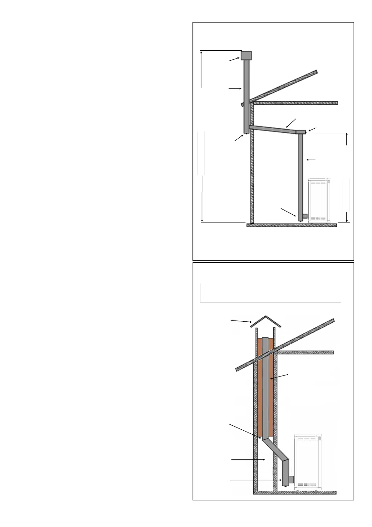
INSTALLATION EXAMPLES OF THE CHIMNEY FLUE
Use only stainless steel tubes.
Do not use synthetic materials or aluminium.
All sections of the fume exhaust must be accessible for inspections and
internal cleaning.
For an external installation, use an insulated chimney flue that can be
inspected on the curves.
The following are a few examples:
DIMENSIONAL LIMITS
CHIMNEY FLUE INSIDE AN OLD CHIMNEY
CORRECT
INSTALLATION
PROTECTION
CAP
INSULATED
CHIMNEY
FLUE
INSULATED “T” WITH
INSPECTION CAP
MAXIMUM LENGTH OF HORIZONTAL
STRETCH 3 METERS
MINIMUM SLOPE 5%
“T” WITH
INSPECTION
CAP
CHIMNEY
FLUE
“T” WITH
INSPECTION CAP
MINIMUM TOTAL HEIGHT 4 METERS
MINIMUM HEIGHT 1,5 METERS
CHIMNEY WITH
COVER PLATE
INSULATION
OPEN 45°
CURVE
OLD
CHIMNEY
FLUE
“T” WITH
INSPECTION
CAP