4
AIR INTAKE
The stove’s air intake is important just as the chimney flue. Infact it is
from this vent where the stove draws the oxygen necessary for the com-
bustion.
The air required for the combustion must be drawn directly from the
outside through a tube with a 60mm diameter. The tube must not exceed
5m in length and must not have more than 4 curves with a 90° angle
(see the example in Figure 4).
Figure 3
Figure 4
A negative combustion means a poor circulation of air in the home and
this often occurs in modern buildings that have sealed doors and win-
dows. The situation becomes more problematic when there are air ex-
tractors within the room. To avoid such a problem, it is recommended to
create an opening a hole on the wall so that the combustion air can enter
the room, this is necessary for both health and safety reasons. It is rec-
ommended the installation of an air grid over the opening and it must be
kept clean.
- DESCRIPTION OF GENERAL FEATURES
FIRST IGNITION AND TESTING
The first ignition is the technicians most important task.
The expense of this operation is on the customers behalf.
Before the first ignition, the technician must first verify the conditions of
the electrical system and the chimney flue, documenting everything on
the appropriate FIRST IGNITION AND TESTING FORM
• Once the ignition procedure has started, the system runs a
check-up on the sensors, the safety features and on the FCS if it
is installed. Completed this phase, the system begins to erogate
pellets for an amount of time that varies from model to model
and activates the ignition resistance. Wait until a flame appears.
• Once the stove is in the Work mode, combustion tests on power
levels P1, P3 and P5 have to be performed. Note that the
change from one power level to another is not immediate.
• The Modulation mode is equal to P1 power setting, to test it, set
the power level on P1 for 10 minutes.
The type of pellets used may be very influential on the quality of the
combustion. For a perfect combination of fuel and combustion air, follow
these steps:
• After the ignition, when the stove is in the Work mode, set the
power level to P5 for 10 minutes and verify if the flame is tall,
just touching the roof of the combustion chamber.
• Then, set the power level to P1 for another 10 minutes and
verify if the flame is low.
If the flame does not comply with the conditions described, then it would
be necessary to adjust the combustion (see COMBUSTION AND AD-
JUSTMENTS page 11).
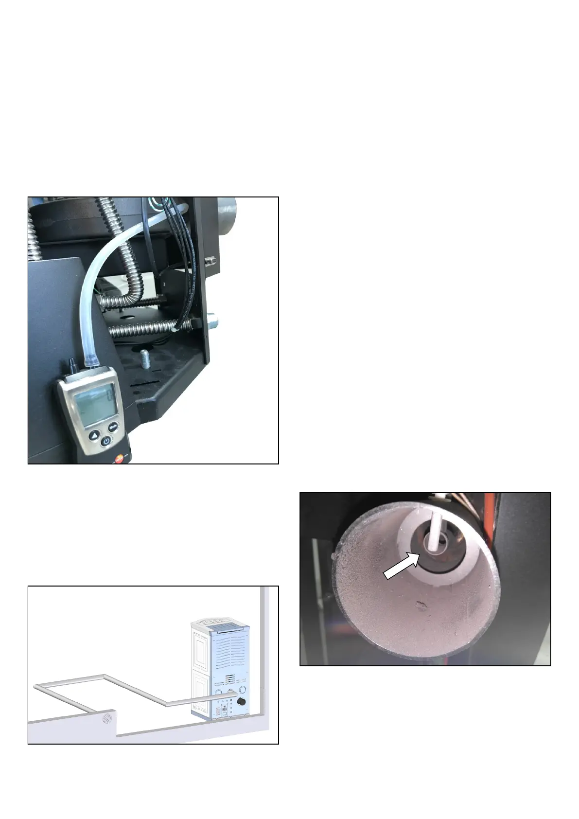
FCS (FIRE CONTROL SYSTEM)
It is an automatic control system that uses a flowmeter to read the condi-
tions in terms of the combustion in the stove.
In order to confirm if the FCS device has been installed on the appliance:
Figure 5
• Measure the draw in Pascal when the stove is off and when it is
on (Run mode).
This measurement allows us to control the draw of the chimney flue. It is
very important to measure the draw when the stove is off and when it is
on.
• If the value read is more or equal to 0, the chimney flue has a
draw.
• If the value read is negative (-), the chimney flue has no draw.
• If the stove is on (Run) and the value read is still negative (-),
there is a scarce draw.
• If the value reaches - 60 Pa, the stove (once the silicone tube
has been reconnected to the exhaust outlet), will go in error
SIC02 (see PRESSUER SWITCH page 05).