Do you have a question about the Moretti Forni PM 60.60 and is the answer not in the manual?
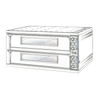
Details the components and features of the cooking element, optional leavening compartment, and their internal structures.
Lists the European directives that the equipment conforms to, ensuring compliance with safety and electromagnetic compatibility standards.
Describes the intended operational environment and how operators interact with the appliances' control switchboards and doors.
Lists the available models of the appliance, differentiating between PM, PD, and iD series with their respective configurations.
Refers to tables containing detailed technical specifications, likely including power, absorption, and voltage ratings.
Provides information on the physical dimensions and weight of the appliance, referencing a figure for details.
Explains how to identify the appliance, emphasizing the importance of the serial number found on the rating plate for communication.
Notes the presence of safety warning labels on the appliance at specified points, indicating potential hazards.
Details the standard delivery method of the appliance, usually on wooden pallets, with protection for individual parts.
Provides instructions for safe unloading, emphasizing the use of specified lifting points and avoiding dragging.
Recommends optimal operating temperature and relative humidity limits for proper oven performance.
Outlines critical safety and regulatory requirements for positioning, assembly, and installation, including distances and ventilation.
Step-by-step guide for assembling the support structure, including attaching tubular elements and ensuring stability.
Instructions for connecting the vapour exhaust pipe, specifying diameter requirements and condensation management.
Detailed guidance for electrical connection of the baking chamber, including switch requirements and cable specifications.
Instructions for electrically connecting the leavening compartment, including switch requirements and cable specifications.
Describes how to connect a rubber tube to a specific connector for draining condensation, aiding appliance maintenance.
Essential checks before starting up the oven, covering electrical, earthing, and vapour exhaust connections by qualified personnel.
Guides the user through the process of starting the baking chamber, including setting temperatures and understanding indicator lights.
Explains the operation of the electromechanical control panel, detailing the function of each thermostat, pyrometer, and switch.
Details the operation of the electronic control panel, including setting temperatures, using display indicators, and understanding safety thermostats.
Describes how to activate and use the Smart Baking mode for setting single temperature and power levels for floor and ceiling.
Provides instructions for operating the leavening compartment, including turning it on, setting temperature, and internal lighting.
Guides the operation of the leavening compartment with humidifier, including filling the tray, setting humidity, and turning elements on/off.
Instructs on how to properly stop the oven and leavening compartment, including disconnecting the power supply.
Essential safety precautions before performing any maintenance, including disconnecting power and using protective equipment.
Daily cleaning procedures for the appliance, emphasizing removal of residues, use of appropriate cleaning agents, and drying.
Recommendations for maintaining the appliance during long periods of non-use, including disconnection, covering, and ventilation.
Highlights that special maintenance must be performed by licensed technicians with proper safety equipment and accident prevention measures.
General cleaning guidelines for internal and external parts, stressing the importance of regular fat and grease removal.
Introduces the procedures for replacing various components within the baking chamber, starting with basic parts.
Step-by-step instructions for replacing the light bulb inside the baking chamber, including cover removal and replacement.
Procedure for replacing the tempered glass in the oven door, involving removal of panels and screws.
Instructions on how to replace the refractory floor of the baking chamber, detailing levering and replacement steps.
Guidance on replacing electrical heating elements for different model series, involving panel and insulation removal.
Detailed procedure for replacing door springs, covering screw management, spring tension adjustment, and lubrication.
Instructions for replacing the main electrical switch on the appliance for both electromechanical and electronic versions.
Procedure for replacing the indicator pyrometer and its sensor, including removal of insulation and control panel screws.
Steps for replacing the thermostat and its sensor, involving access through the electrical panel and insulation removal.
Guidance on replacing the digital pyrometer, including removing the front panel, casing, and disconnecting electrical connectors.
Instructions for replacing the thermocouple, involving side panel removal, inner casing access, and connector disconnection.
Procedure for replacing the safety thermostat, including side panel removal, thermostat sensor access, and connector disconnection.
Steps for replacing the transformer, requiring rear panel removal and disconnection of its electrical connections.
Instructions for replacing the main switch for the electronic version, involving side panel removal and connector disconnection.
Introduces procedures for replacing components specific to the leavening compartment assembly.
Guidance on replacing the heating element in the leavening compartment tray, involving screw and wire disconnection.
Instructions for replacing the light bulb and/or cover within the leavening compartment, requiring cover removal.
Procedure for replacing the ball knob on the leavening compartment, involving door opening and nut unfastening.
Steps for replacing the thermostat dial and its ring nut on the leavening compartment, requiring snap-on dial removal.
Instructions for replacing the magnetic door fastener on the leavening compartment, involving snap ring removal.
Procedure for replacing the thermostat in the leavening compartment, detailing panel removal and sensor access.
Details the essential information required when ordering spare parts, such as appliance type and serial number.
Provides an index of the plates corresponding to different appliance assemblies and components, guiding spare parts identification.
| Brand | Moretti Forni |
|---|---|
| Model | PM 60.60 |
| Category | Kitchen Appliances |
| Language | English |