
A
Angel BrownAug 9, 2025
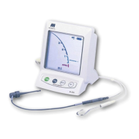
What to do if the Canal Length Indicator doesn't move on my Morita DENTA PORT ZX Dental equipment?
- BBrian HarveyAug 9, 2025
The canal length indicator may not move at all, or only when the file tip is close to the apical foramen if the canal is blocked, the apical foramen is very large and open, or the canal is extremely dry. To resolve this, open the passage all the way through the apical constriction first and then take the measurement. If the apical foramen is large or wide open and not completely formed, the canal length indicator bar will suddenly jump when the file tip gets close to the apex. Moisten the canal with oxydol or a saline solution.