Do you have a question about the Morningstar SureSine 150 W and is the answer not in the manual?
| Brand | Morningstar |
|---|---|
| Model | SureSine 150 W |
| Category | Inverter |
| Language | English |
General safety guidelines for installation and operation, adhering to NEC codes.
Installations must be by qualified personnel; comply with local codes.
Over-current protection and wiring must be sized properly per NEC.
Risk of fire if 120 Vac power is wired incorrectly to a 120/240 Vac panel.
Avoid confined areas; ensure ventilation; do not mount over combustible surfaces.
Ensure adequate space for ventilation; protect from environmental factors.
Battery servicing by knowledgeable personnel; precautions for electrical shock/burns.
Ensure adequate ventilation for charging; proper battery disposal and no smoking.
Handle batteries carefully; wear protective gear; avoid contact with acid.
Match battery voltage; use same type/age batteries; do not charge frozen batteries.
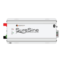
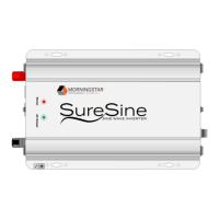
Lists key features of the SureSine inverter, including power conversion and communication.
Details the components and ports for the 150W and 300W models.
Details the components and ports for the 700W models.
Details the components and ports for 1000W to 2500W models.
Provides physical dimensions and diagrams for 150W and 300W models.
Provides physical dimensions and diagrams for 700W to 2500W models.
Lists essential tools for installing the SureSine inverter, including safety notes.
Lists required hardware not included with the inverter for installation.
Safety warnings and guidelines for mounting, including clearance and ventilation.
Identifies the location of the DIP switches on the DC side of the unit.
Details the function and settings for each of the 8 DIP switches.
Specifies torque values for various terminal connections according to Table 3.
Requirements for DC and AC over-current protection devices (fuses/breakers).
Guidelines for selecting DC and AC conductor sizes based on NEC standards.
Requirements for a proper grounding system for safety and protection.
Instructions for removing the internal bond for external grounding configurations.
Details on making chassis, DC neutral, and AC neutral ground connections.
Instructions for connecting the chassis grounding terminal to earth ground.
Ensures the DC system ground is properly bonded to ground per NEC.
Safety warnings about DC cable connections and potential hazards.
Wiring diagrams for NEGATIVELY grounded DC wiring configurations.
Wiring diagrams for POSITIVELY grounded DC wiring configurations.
Step-by-step procedure for making DC connections, including safety.
Requirement for an external GFDI device as per NEC Article 690.
Precautions regarding AC load ratings, surge currents, and voltage compatibility.
Step-by-step procedure for connecting AC wiring to the inverter.
Warning regarding explosion risk when connecting the battery under certain conditions.
Explains the meaning of the Status and AC Output LEDs on the inverter.
How to operate the AC Output Mode Switch for direct or remote control.
Describes the Low Voltage Disconnect feature and audible warnings.
Explains the High Voltage Disconnect feature for battery overvoltage.
Describes the High Temperature Disconnect feature for overheating.
Details over-current and short-circuit protection, including retry mechanisms.
Explains Bluetooth connectivity for mobile device control and monitoring.
Steps to establish a Bluetooth connection between a mobile device and the inverter.
Details the SureSine Utility App availability and features for Android/Apple.
Information on Ethernet port for Modbus TCP/IP communication.
Steps to connect the inverter to a network via Ethernet using Modbus.
Details EIA-485 communication standard for networking devices.
Instructions for connecting the SureSine to EIA-485 devices.
Details the USB port for firmware updates on specific models.
Instructions for connecting a USB device and activating firmware updates.
Information about the future MS-CAN communication feature.
Steps to connect the SureSine to another Morningstar device via MS-CAN.
Steps for connecting the SureSine in a multi-device MS-CAN network.
Provides maximum 1-way distance for 2% voltage drop with 12V system.
Provides maximum 1-way distance in meters for 2% voltage drop with 12V system.
Steps to follow when requesting warranty service for the inverter.
Conditions under which the warranty is not applicable.