Do you have a question about the Morningstar ProStar and is the answer not in the manual?
Explains how to correctly wire positive grounded systems to avoid bypassing switching circuits.
Discusses chassis grounding for surge protection and code compliance.
Covers NEC allowances for single-pole breakers on ungrounded conductors in communication wiring.
Discusses GFPS for detecting and interrupting ground faults in PV circuits.
This document outlines the use of Morningstar solar charge controllers in telecom applications, particularly focusing on positive ground (PG) systems. These controllers are designed to manage power flow from solar arrays to battery banks and loads, ensuring efficient and reliable operation for various system sizes.
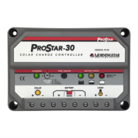
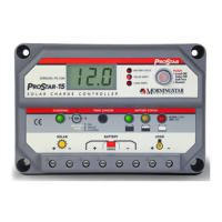
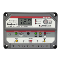
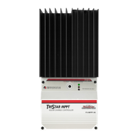
Morningstar solar charge controllers, including the ProStar, ProStar MPPT, TriStar, and TriStar MPPT models, are designed to regulate the charging of battery banks from solar arrays and manage power delivery to connected loads. They are suitable for a range of power requirements, from low-power 24V systems to higher-power 24V or 48V systems. For very high-power systems, multiple controllers can be configured in parallel to meet demand. A key feature is the inclusion of digital data output, which allows for monitoring of system performance and available power, making them well-suited for telecom sites that require detailed operational data.
While Morningstar controllers are typically designed for negative ground systems, they can be effectively integrated into positive ground (PG) circuits, which are common in many DC telecom systems. In a negative ground system, the negative terminals of the controllers are electrically common, and charge control switching occurs in the positive leg of the circuit. This common negative allows for a single negative ground bond for the entire system, encompassing the solar array, battery, and load. An exception to this single ground bond rule might be to provide separate ground bonds at the PV array and the controller to mitigate voltage surges from lightning, though this is not feasible for systems with ground fault protection, as it would trigger the protection.
For positive ground systems, the wiring is largely similar to negative ground systems, but a critical consideration is to avoid connecting a positive ground bond to two separate circuits. For instance, if the positive leg of the battery is grounded, the positive legs of the PV array or the load should not be grounded. Doing so would create a positive ground connection that bypasses the controller's positive switching circuit, leading to uncontrolled charging from the solar array to the battery or uncontrolled power delivery from the battery to the load, effectively disabling charge or load control. The only scenario where a permanent common positive connection between the battery and load is permissible is if a load control relay switch is used on the negative conductor of the load circuit. Morningstar controllers with load control typically feature a common negative with positive switching.
The document also addresses the proper grounding of telecom loads. To maintain a grounded telecom load during operation, the positive ground must be connected to either the battery circuit or the load circuit. If the positive ground is connected only to the PV array circuit, the battery and load will not have a positive ground. Since Morningstar controllers with load control have a common negative, disconnecting the load would also unground it. However, telecom equipment typically does not require a positive ground when disconnected. If this is a concern, grounding the load circuit is an option.
Morningstar controllers offer flexibility in system design and grounding configurations. Their ability to operate in both negative and positive ground systems makes them versatile for various telecom infrastructure requirements. The digital data output is a significant usage feature, providing valuable insights into system performance, which is crucial for remote monitoring and maintenance in telecom applications.
The controllers are designed with a common negative for their power circuits, as well as for their communication ports (MeterBus RJ-11, MODBUS Serial RS-232, and EIA-485). This common negative connection is important when considering disconnect and overcurrent protection. In certain communication configurations, using single-pole battery breakers, switches, or fuses on the negative power conductors can be problematic. This is because the disconnect switches could be bypassed through the communication wiring, potentially causing damage due to unintended current paths through the smaller communication circuits.
Specific scenarios where single-pole disconnects on the ungrounded conductor might cause issues include EIA-485 MODBUS networks, Ethernet MeterBus Converter (EMC-1) systems, systems with Relay Driver(s) using an RJ-11 MeterBus connection, and RS-232 MODBUS connections to third-party devices. In these cases, the communication wiring creates a common negative connection between controllers or devices. A single-pole breaker on the negative conductor would not break this common negative connection, potentially leading to damage. Therefore, using double-pole breakers that disconnect both the positive and negative conductors is recommended to ensure independent disconnection of each controller without harming serial communications. For the EMC-1, a fuse for its power circuit should be installed on the positive wire. Using an isolated RS-232 device is another option for RS-232 connections.
The design of Morningstar controllers, particularly their chassis isolation from DC circuits, simplifies maintenance and grounding requirements. The chassis can be grounded in the same manner for both positive and negative ground systems. Chassis grounding is often mandated by electrical codes and is essential for surge protection devices to function correctly, limiting voltage surges from lightning strikes. Many Morningstar controllers include a dedicated chassis ground terminal; if not, an equipment grounding conductor can be wired directly to the chassis. Users are advised to consult the product manual for detailed information on equipment grounding and to adhere to local electrical code requirements.
Ground Fault Protection (GFP) is another important maintenance-related feature. Morningstar's GFP products (GFPD-150V and GFPD-600V) are compatible with both negative and positive grounded systems. They detect and interrupt ground fault currents that may occur in the PV circuit. For effective operation, especially in positive grounded systems using a load controller that can break the positive leg, the system should be grounded on the battery circuit or PV array circuit, not on the load circuit. If the system is grounded at the load and the load is disconnected, the PV array and battery would not be grounded, rendering the ground fault protection ineffective.
The recommendation to use double-pole breakers for disconnecting both positive and negative conductors in communication-intensive setups is a key maintenance consideration. This ensures that controllers can be safely isolated for service or troubleshooting without risking damage to sensitive communication circuits. This approach helps prevent unintended current paths and protects the integrity of the system's electronics.
| Waveform | Pure Sine Wave |
|---|---|
| Input Voltage | 12V, 24V, 48V |
| Output Voltage | 120 VAC or 230 VAC (depending on model) |
| Protections | Overload, over temperature, low battery voltage, high battery voltage, short circuit |
| Efficiency | >90% |