7
Assembly
THROTTLE CABLE AND IGNITION WIRES
(BC 260 S2 and BC 325 S2 only)
1. Connect the two ignition wires running from the trigger grip to
the two wires on the engine. (The order does not matter).
2. Remove the engine air cleaner cover and pass the end of
the throttle wire through the brass adjusting nut on top of the
carburettor.
3. Hold the carburettor butterfly fully open and drop the throttle
wire into the slot of the wire anchor, making sure that the
bulb on the end of the wire fits into the end of the slot that is
enlarged.
(1) Wire anchor
(2) Choke lever
(3) Adjusting nut
4. Check that, when the trigger grip is in the released (idle)
position, there is 1 or 2 mm slack in the throttle wire.
5. Alter the brass adjusting nut if necessary to achieve this.
6. Refit the air cleaner cover.
HANDLE (BC 325 S2 only)
1. Loosen the 4 bolts on the handle bracket.
2. Insert the right handle (the one with the trigger grip) and the left
handle assembly into the bracket as illustrated and retighten
the bolts securely.
(1) Handle bracket
(2) Right handle
(3) Bolt
(4) Left handle
(5) To the engine
SAFETY GUARD
Attach the safety guard to the lower end of the main tube. The
BC 230B S2 and BC 260B S2 guard is fastened with two Do
not operate this unit without a safety guard, if the safety guard is
damaged replace immediately. Do not continue with a damaged
guard.
(1) Bolt
(2) Clamp
(3) Main tube
(4) Safety guard
Do not operate this unit without a safety guard, if the safety
guard is damaged replace immediately. Do not continue with
a damaged guard.
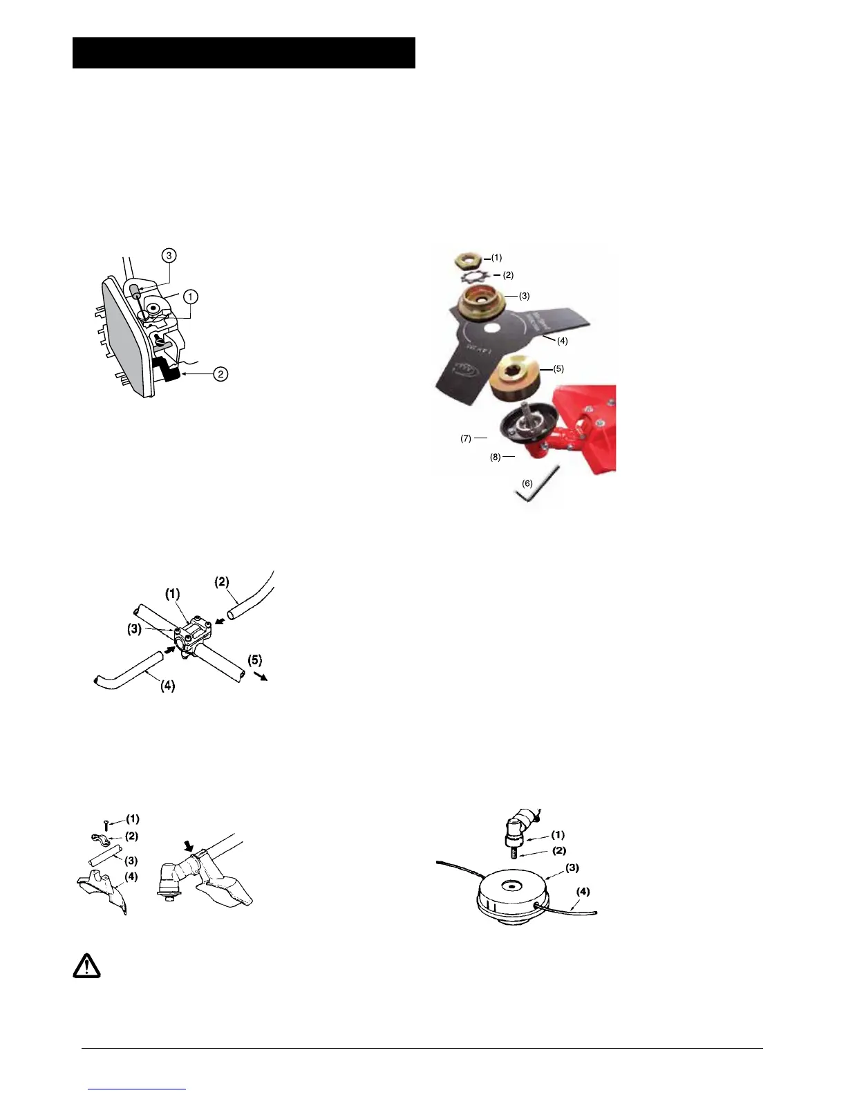
INSTALLING THE METAL BLADE (not included in all models)
(BC 260 S2 and BC 325 S2)
1. Turn the inner flange until it can be locked in position with the
‘L’ shaped locking bar inserted through the outer shroud.
2. Blades can only be used on straight shaft models blade to
the projection on the inner flange. In the case of Put the blade
on the inner flange, matching the hole in the the 80 & 8 tooth
blades, ensure that the numbers stamped on the blade are
toward the gear case. The 3 tooth blade can go either way and
can be reversed when one set of cutting edges is blunt.
3. Fit the flange outer over the gear shaft.
4. Fit the Locking washer onto the outer flange, then fit and
tighten the left hand threaded retaining nut. (Turn anticlockwise
5. to tighten).
(1) Nut
(2) Locking washer
(3) Flange outer
(4) Blade
(5) Flange inner
(6) Locking bar
(7) Outer shroud
(8) Gear case
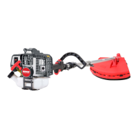
INSTALLING THE NYLON CUTTER
(BC 230B S2 and BC 260B S2)
1. Screw the nylon cutter head clockwise onto the shaft. (The
black head has a RIGHT HAND THREAD).
2. When the cutter head reaches the hexagon fitting, use a
spanner on the hexagon to hold it while turning the cutter head
clockwise as far as possible by hand.
INSTALLING THE NYLON CUTTER HEAD
(BC 260 S2 and BC 325 S2)
1. Make sure the inner flange is fitted correctly on the gear shaft
and turn it until it can be locked in position with the ‘L’ shaped
locking bar inserted through the outer shroud.
2. Screw the nylon cutter head anti-clockwise onto the shaft,
because it has LEFT HAND THRE AD.
3. Use the ‘L’ shaped bar to prevent the inner flange from turning
while screwing the nylon cutter assembly onto the shaft.
Hand tighten only.
(1) Gear Case
(2) Shaft
(3) Nylon cutter head
(4) Nylon cord