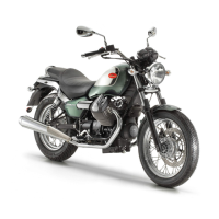
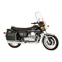
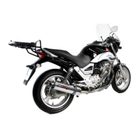
Do you have a question about the MOTO GUZZI V 35 and is the answer not in the manual?
Procedure for checking and changing engine oil levels and quantities.
Steps to replace the oil filter cartridge in the oil sump.
Instructions for dismantling, cleaning, and reassembling the oil sump and wire gauze filter.
Procedure for checking and changing the gearbox oil level and quantity.
Procedure for checking and changing the rear drive box oil level and quantity.
Steps for draining and refilling the front fork oil.
Periodic lubrication points for various motorcycle components.
Description of panel board indicators, warning lights, and their functions.
Explanation of the ignition key positions and their functions.
Location and operation of the light switches on the left handlebar.
Operation of horn, flash light, and turn signal controls on the handlebar.
Procedure for starting the engine and using the emergency stop switch.
Description of the right front brake control lever on the handlebar.
Location and function of the combined front left and rear brake control pedal.
Operation of the gear control pedal on the left side of the machine.
How to open the fuel filter cap.
Procedure for checking the brake fluid level in the reservoir.
Description of the fuel tap positions (ON, RES, OFF).
Location and identification of fuses in the terminal block.
Instructions for locking and unlocking the steering.
Procedure for unlocking and locking the seat.
Information on the side stand, including types and usage.
Procedure for adjusting the play in the clutch control lever.
Procedure for adjusting the play in the right front brake lever.
Checking and adjusting play in the linkage for left front and rear brake pedal.
Adjusting the travel of the twist grip and its return.
Procedure for adjusting steering to eliminate excessive play.
Ensuring the swinging arm oscillates freely without play.
Procedure for adjusting the external spring of the rear suspension.
Procedure for adjusting rocker clearance on a cold engine.
Schedule of lubrication and maintenance tasks with recommended intervals.
Procedure for removing the engine-gearbox assembly from the frame and separating them.
Instructions for removing the rocker box covers.
Procedure for dismantling the cylinder heads, including valve removal.
Procedure for removing the cylinder barrels and checking them.
Procedure for removing piston rings and oil scrapers.
Procedure for removing pistons from the engine, including checking operations.
Procedure for separating the crankcase covers.
Procedure for replacing the seal in the timing cover while the engine is mounted.
Procedure for dismantling connecting rods.
Procedure for dismantling the crankshaft.
Procedure for removing the flywheel.
Procedure for dismantling the ignition group.
Procedure for removing the engine oil sump.
Procedure for dismantling the oil pump.
Procedure for removing the oil pressure relief valve.
Function of the oil pressure warning light switch.
Procedure for removing the oil filter cartridge from the sump.
Procedure for removing the wire gauge filter from the oil sump.
Description of the Dell'Orto carburetors and their controls.
Specifications for carburetor settings (jet sizes, needle position, etc.).
Procedure for leveling the carburetor float.
Steps for adjusting carburetor and idling speed.
Procedure for adjusting carburation using a vacuum gauge.
Detailed procedure for dismantling a carburetor.
Components and removal of the air filter and breather unit.
Procedure for removing the clutch assembly.
Inspection of clutch components for wear or damage.
Procedure for removing the gearbox and swinging arm.
Procedure for removing and inspecting the clutch housing.
Procedure for removing and inspecting the clutch.
Procedure for dismantling the gearbox.
Procedure for removing and inspecting the gearbox cover.
Procedure for dismantling and reassembling the gear-shafts.
Procedure for dismantling, inspecting, and reassembling the gear selector.
Procedure for dismantling the kickstarter mechanism.
Inspection of kickstarter components for wear or damage.
Procedure for removing the swinging arm and rear drive box.
Inspection of the swinging arm and drive box components.
Procedure for removing the bevel pinion housing from the drive box.
Procedure for removing brake disc, cover, spindle, crown wheel, bearings, and seals.
Procedure for adjusting pinion-wheel coupling clearance.
Procedure for removing and re-assembling the swinging arm.
Procedure for removing the entire frame unit.
Inspection of frame components and electricals.
Procedure for removing the front fork assembly from the motorcycle frame.
Procedure for reassembling the front fork assembly.
Procedure for removing the fork sleeve from the fork.
Procedure for removing the rear shock absorbers from the frame.
Inspection of rear suspension springs and shock absorbers.
Procedure for dismantling the steering assembly.
Inspection of steering components for wear or damage.
Procedure for removing the front wheel from the fork.
Procedure for removing the front wheel hub.
Procedure for removing the rear wheel from the swinging arm.
Procedure for removing the rear wheel hub.
Information on tire types, recommended pressures, and wear.
Procedure for balancing wheels when a machine is unavailable.
Recommendations for removing and refitting tires to avoid damage.
General maintenance for front and rear brake circuits.
Procedure for putting a new dry battery into service.
Procedure for measuring electrolyte specific gravity and temperature.
Method for correcting specific gravity readings based on temperature.
Main features and testing procedure for the alternator.
Main features of the voltage regulator.
Brand information for the rectifier.
Main features and electric tests for the starter motors.
Information on the electronic ignition system, operation, and warnings.
Procedure for manually adjusting ignition timing.
Using a special tool to adjust ignition timing.
Using a strobe lamp to check ignition timing.
Recommended spark plug brands, gap, and replacement.
Description and specifications of the headlight.
Procedure for replacing headlight bulbs.
Location and bulb replacement for the tail light.
Description and location of front and rear turn signal lights.
Procedure for replacing bulbs in the panel board instruments.
List of bulb types and wattages for various lights.
Brand and current absorption of the horn.
Troubleshooting and repair of the horn.
Ensuring cable condition and proper accessory connections.
| Displacement | 346 cc |
|---|---|
| Transmission | 5-speed |
| Front Brakes | Single disc |
| Rear Brakes | Drum |
| Cooling System | Air |
| Final Drive | Shaft |
| Frame type | Steel |
| Front Suspension | Telescopic forks |
