EasyManua.ls Logo

Motor Saver 201A-AU User Manual

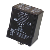
Motor Saver 201A-AU
12 pages
To Next Page IconTo Next Page
Page #1 background imageLoading...
Page #1 background image
INSTALLATION
INSTRUCTIONS
2880 North Plaza Drive, Rapid City, South Dakota 57702
(800) 843-8848 · (605) 348-5580 · fax (605) 348-5685
MODELS 201A-AU
201-575-AU
Revision B1
Rapid City, SD, USA, 02/2010
II_201A-AU_B1

Questions and Answers:

Motor Saver 201A-AU Specifications

General IconGeneral
BrandMotor Saver
Model201A-AU
CategoryAccessories
LanguageEnglish

Summary

Installation Instructions

Connections

Step-by-step guide for wiring the MotorSaver unit into the motor control circuit.

Settings

Setting Adjustment Controls

Guide to adjusting Line Voltage, Restart Delay, Trip Delay, and Voltage Unbalance settings.

Voltage Unbalance Calculation

Explains the NEMA MG1 formula for calculating % voltage unbalance with an example.

Operation

Automatic Reset Mode

How the MotorSaver operates in automatic reset mode after a fault.

Manual Reset Mode

How the MotorSaver operates in manual reset mode and requires manual intervention.

Troubleshooting

Dead Unit / No Lights

Diagnosing issues when the unit shows no power or activity.

Initial Power-up Faults

Troubleshooting initial power-up issues, including dead unit and blinking red light.

Phase and Voltage Faults

Troubleshooting issues related to phase reversal, unbalance, and voltage levels.

Operational Status Issues

Diagnosing problems when the motor is not running or not starting correctly.

Dimensions

Specifications

Functional Characteristics

Details trip/reset points for low voltage, high voltage, and voltage unbalance.

Input Characteristics

Specifies line supply voltage and frequency requirements for the unit.

Output Characteristics

Defines the contact rating for pilot duty and general purpose applications.

General Characteristics

Covers environmental, safety, dimensions, weight, and mounting specifications.