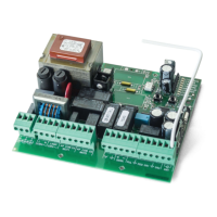
ELECTRONIC CONTROL UNIT MC2
Single-phase electronic control unit for the automation of
swinging gates with incorporated radio receiver.
TECHNICAL DATA:
- Power supply : 230 Vac 50-60Hz 1600W max.
- Flashing beacon output : 230 Vac 500 W max.
- Motor outputs : 230 Vac 500 W max.
- Electric lock output : 12 Vdc 15 W max.
- Photoelectric cells power supply: 24 Vac 3 W max.
- Low voltage safety features and commands : 24 Vcc
- Operating temperature : -10 ÷ 55° C
- Radio receiver : 433,92 MHz
- Op. transmitters : 12-18 Bit or Rolling Code
- Max TX stored codes : 150 (CODE or CODE PED)
- Container size : 190x140x70 mm.
- Protection degree : IP 56
TERMINAL BOARD CONNECTIONS:
CN1:
1 : 230 Vac line input (Phase).
2 : 230 Vac line input (Neutral).
3 : 230 Vac Flashing Beacon output (Neutral).
4 : 230 Vac Flashing Beacon output (Phase).
5 : Motor 1 opening output.
6 : Motor 1 common output.
7 : Motor 1 closing output.
5 : Motor 2 opening output.
6 : Motor 2 common output.
7 : Motor 2 closing output.
CN2:
1 : Photoelectric cells control and power supply (24 Vac).
2 : Photoelectric cells control and power supply (GND).
3 : 12 Vdc 15 W (+12V) electric lock output.
4 : 12 Vdc 15 W (GND) electric lock output.
5 : PUL open-close command button input (NA).
6 : GND common input.
7 : PUL PED pedestrian command button input (NA).
8 : DS1 safety device input (NC).
9 : GND common input.
10 : DS2 safety device input (NC).
11 : Antenna earth input.
12 : Antenna hot pole input.
FUNCTIONAL DATA:
Automatic Operation:
Using both the radio control (CODE LED on) and the low
voltage push-button station (PUL) to control the shutter, the
following operation is obtained:
the first impulse opens the shutter until the end of the motor
time, the second impulse closes it; if an impulse arrives before
the end of the motor time, the control unit inverts motion both
during opening and closing.
Step-by-Step Operation:
Using both the radio control (CODE LED on) and the low
voltage push-button station (PUL) to control the shutter, the
following operation is obtained:
the first impulse opens the shutter until the end of the motor
time, the second impulse closes it; if an impulse arrives before
the end of the motor time, the control unit stops motion both
during opening and closing. An additional command restarts
motion in the opposite direction.
Automatic closing:
The control unit can close the shutter automatically without
sending additional commands.
The selection of this operation mode is described in the Pause
Time programming mode.
Pedestrian Passage :
The control unit can operate Motor 1 only both using the radio
control (CODE LED on) and the push-button station (PED) for
the programmed time (T. MOT. PED. LED).
Safety device 1 :
The control unit allows for powering and connecting
photoelectric cells according to EN 12453.
The action is not considered during opening and causes
inverted motion during closing.
The control unit must use photoelectric cells connected to
dedicated inputs; otherwise the control unit is not enabled for
operation.
Safety device 2 :
The control unit allows for powering and connecting
photoelectric cells according to EN 12453.
The action momentarily stops the shutter during opening; after
release, the control unit resumes opening. The action causes
inverted motion during closing.
The control unit must use photoelectric cells connected to
dedicated inputs; otherwise the control unit is not enabled for
operation.
Initial Pick-up and Motor Power Adjustment:
The electronic control unit is equipped with initial pick-up and
motor power adjustment functions that are fully managed by
the microprocessor.
The initial pick-up function is used to help the motor during
initial motion by powering the motor with maximum power for 2
seconds, also when the motor power adjustment function is
enabled.
The motor power adjustment function is used to ensure correct
motion and at the same time block the shutter in case of
obstacles without causing harm to individuals or properties.
Deceleration:
The motor deceleration function is used to avoid high-speed
closing of swinging gates at the end of opening and closing.
Deceleration can be programmed at the desired points before
total opening and closing during Motor Time programming.
Flashing Beacon Operation:
The control unit is equipped with output for 230 Vac flashing
beacon. Operation is determined by the motion of the motor
and automatic closing that, if enabled, activates the flashing
beacon also during the pause.
Operation with TIMER:
The control unit allows for connecting a timer instead of the
open-close command button (PUL).
Example: 8:00 a.m. the timer closes the contact and the control
unit commands opening, 6:00 p.m. the timer opens the contact
and the control unit commands closing. From 8:00 a.m. to 6:00
p.m. at the end of opening the control unit disables the flashing
beacon, the automatic closing and the radio controls.
PROGRAMMING :
SEL key: it selects the type of function to store, selection is
indicated by flashing LED.
By pressing the key repeatedly, you can select the desired
function. The selection remains active for 10 seconds (flashing
LED); after 10 seconds, the control unit returns to the original
status.
SET key : it programmes the information according to the type
of function selected with the SEL key. IMPORTANT: The
GB