EasyManua.ls Logo

Motorola BDA Series - User Manual

Motorola BDA Series
2 pages
Print Icon
To Next Page IconTo Next Page
Loading...
4 BDA • Broadband Telecommunications Drop Amplifier
Installation
To install a BDA-** drop amplifier using local power:
1. Remove and discard the port thread protectors.
2. Connect the amplifier RF output ports (RF output 1, 2, 3, 4) to your
televisions or set-top terminals using coaxial cable terminated with F-type
connectors.
3. Terminate all unused ports with 75 ohms for optimum RF performance.
4. Connect the coaxial cable-in source to the RF input port of the amplifier.
5. Connect one end of the coaxial cable to the AC adapter and the other end to
the power 12 VDC (18 VDC) connector on the amplifier.
6. Plug the AC adapter into the wall outlet. The LED on the BDA-** should be lit
to indicate that the unit is receiving 12 VDC (S-series) or 18 VDC (K-series).
Figure 5 — Local-power installation with a 12 VDC power supply
Question and Answer IconNeed help?

Do you have a question about the Motorola BDA Series and is the answer not in the manual?

Summary

BDA Amplifier Installation

Local-Power Installation

Steps for installing the BDA amplifier using a local 12 VDC power supply, including connecting cables and powering the unit.

Remote-Power Installation

Remote-Power Setup

Guide to installing the BDA amplifier remotely using a power inserter and coaxial cable for power transmission.

Overview

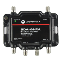
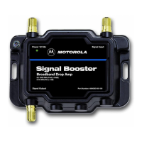
The Motorola BDA-S1 is a broadband drop amplifier designed to improve RF signal quality for televisions and set-top terminals. It amplifies signals in the forward path from 52-1000 MHz with a gain of -15dB and in the return path from 5-42 MHz with a gain of -1dB. The device supports both local and remote power installations, offering flexibility in deployment.

Function Description:

The primary function of the BDA-S1 is to boost RF signals, ensuring a strong and clear signal reaches multiple televisions or set-top terminals in a home or office. This is particularly useful in situations where signal strength degrades due to long cable runs, splitters, or multiple connections, leading to poor picture quality or intermittent service. The amplifier features multiple output ports (typically two or four, though the diagrams show a single output for simplicity in some contexts) to distribute the amplified signal to various devices. It also includes an RF input port for the incoming coaxial cable source and a dedicated power input.

Important Technical Specifications:

  • Forward Path Frequency Range: 52-1000 MHz
  • Forward Path Gain: -15dB (This value seems unusual for an amplifier, as amplifiers typically provide positive gain. It might indicate a specific application or a typo in the provided text, where a positive gain value would be more typical for a "drop amp".)
  • Return Path Frequency Range: 5-42 MHz
  • Return Path Gain: -1dB (Similar to the forward path, a negative gain in the return path suggests attenuation rather than amplification, which could be intentional for specific network designs or another potential typo.)
  • Power Input: 12 VDC (for S-series) or 18 VDC (for K-series), supplied via an AC adapter.
  • Port Termination: All unused ports require termination with 75 ohms for optimal RF performance.
  • Connectors: F-type connectors for all RF input and output ports.

Usage Features:

Local Power Installation:

  1. Direct Connection: The amplifier connects directly to the coaxial cable-in source via its RF input port.
  2. Multiple Outputs: RF output ports (1, 2, 3, 4) connect to televisions or set-top terminals using F-type coaxial cables.
  3. Power Supply: A 12 VDC (or 18 VDC) AC adapter plugs into a wall outlet and connects to the amplifier's power input port. An LED on the unit indicates when power is being received.
  4. Unused Port Termination: Any unused output ports must be terminated with 75-ohm terminators to maintain optimal RF performance and prevent signal reflections.

Remote Power Installation (using BDP-100/PI power inserter):

This method is ideal for installations where the amplifier is located remotely (e.g., in a basement or attic) and power is supplied from an AC outlet near the television. This setup helps maintain signal quality by placing the amplifier as close as possible to the cable entrance.

  1. Amplifier Placement: Install the BDA-S1 remotely, close to the cable entrance.
  2. Power Inserter Connection: A coaxial cable connects the amplifier's Remote Power/RF Output port 1 to the RF-PWR port of the BDP-100/PI power inserter.
  3. Output to Devices: The RF OUT port of the power inserter connects to a television or set-top terminal. Additional televisions or set-top terminals connect to the remaining output ports on the amplifier.
  4. Power Inserter Supply: A separate AC adapter connects to the PWR IN port of the power inserter, which then plugs into a wall outlet. The power inserter sends 12/18 VDC power to the amplifier through the coaxial cable connected to Remote Power/RF Output port 1.
  5. Unused Port Termination: All unused ports on the amplifier (except the 12/18 VDC power port, which remains non-terminated in this setup) must be terminated with 75-ohm terminators.
  6. Cable-in Source: The coaxial cable-in source connects to the RF Input port of the amplifier.

Maintenance Features:

  • Port Protection: The device comes with port thread protectors that should be removed during installation.
  • Optimal Performance: Regular termination of unused ports with 75-ohm terminators is crucial for maintaining optimal RF performance and preventing signal degradation.
  • Power Indicator: An LED on the amplifier provides a visual indication of power status, simplifying troubleshooting for power-related issues.
  • Durable Construction: The device is designed for broadband applications, suggesting a robust build suitable for continuous operation in typical residential or commercial environments.

The BDA-S1 is a versatile solution for enhancing broadband signal distribution, offering both direct power and remote power options to suit various installation scenarios while emphasizing the importance of proper port termination for peak performance.

Motorola BDA Series Specifications

General IconGeneral
BrandMotorola
ModelBDA Series
CategoryAmplifier
LanguageEnglish

Related product manuals