Transceiver Performance Testing Setup 3-5
* See Table 3-3
FSK Error DMR Mode. FSK Error TEST MODE,
Digital Mode,
transmit with
O.153 test
pattern
Key up radio with
O.513 test pattern
modulation using
Tuner
Not Exceed 5%
Magnitude
Error
DMR Mode. Magnitude
error
As above As above Not Exceed 1%
Symbol
Deviation
DMR Mode. Symbol
Deviation
As above As above Symbol Deviation
should be within
648Hz +/- 10% and
1944Hz +/- 10%
Transmitter
BER
DMR Mode As above As above Transmitter BER
should be 0%
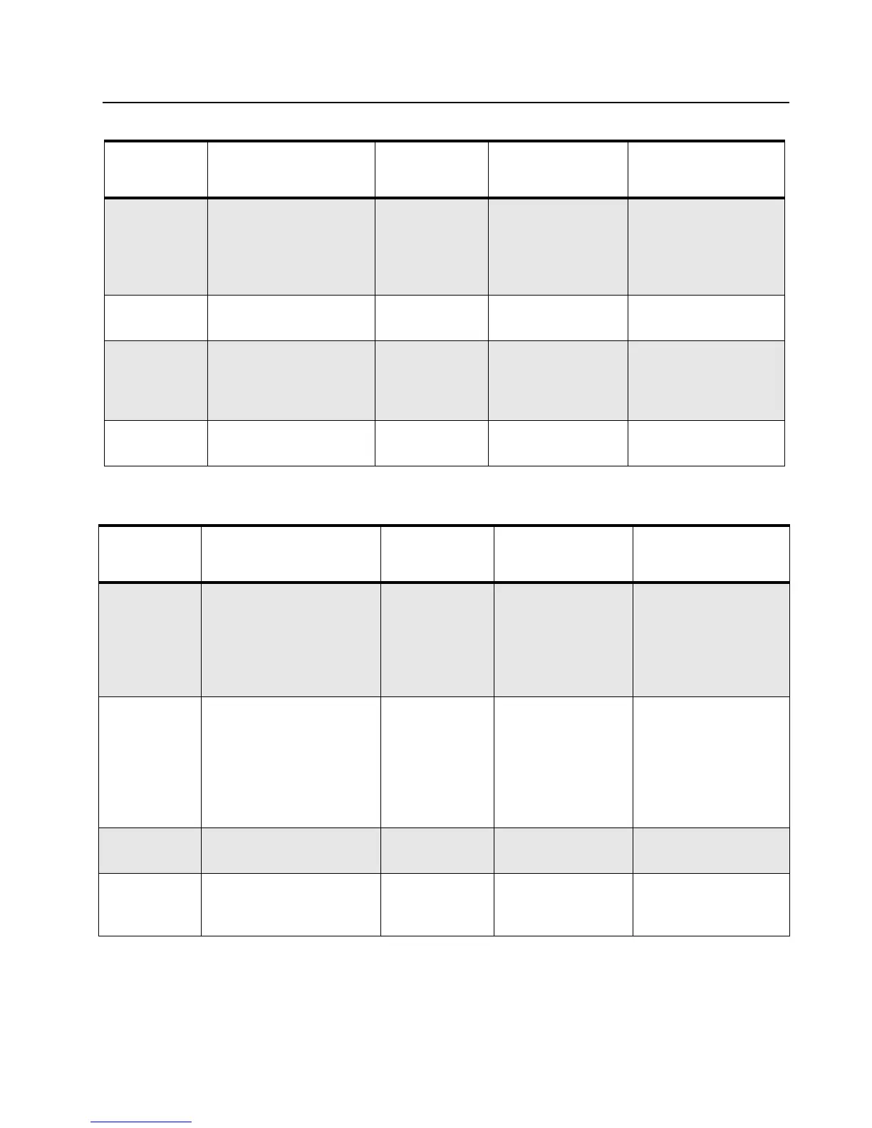
Table 3-5. Receiver Performance Checks
Tes t Nam e
Communications
Analyzer
Radio Test Set Comments
Reference
Frequency
Mode: PWR MON
4th channel test
frequency*
Monitor: Frequency error
Input at RF In/Out
TEST MODE,
Test Channel 4
carrier squelch
output at
antenna
PTT to
continuously
transmit
(during the
performance
check)
Frequency error to be
±68Hz for VHF
±201Hz for UHF
Rated Audio Mode: GEN
Output level: 1.0mV RF
6th channel test
frequency*
Mod: 1kHz tone at
3kHz deviation
Monitor: DVM: AC Volts
TEST MODE
Test Channel 6
carrier squelch
PTT to OFF (cen-
ter), meter selec-
tor to Audio PA
Set volume
control to 2.83 Vrms
Distortion As above, except to
distortion
As above As above Distortion <3.0%
Sensitivity
(SINAD)
As above, except SINAD,
lower the RF level for
12dB SINAD.
As above PTT to OFF
(center)
RF input to be
<0.35μV
Table 3-4. Transmitter Performance Checks
Tes t Na me
Communications
Analyzer
Radio Test Set Comments
 Loading...