3-6 Transceiver Performance Testing Setup
* See Table 3-3
Noise
Squelch
Threshold
(only radios
with
conventional
system need
to be tested)
RF level set to 1mV RF As above PTT to OFF
(center), meter
selection to Audio
PA, speaker/load
to speaker
Set volume
control to 2.83Vrms
As above, except change
frequency to a
conventional system.
Raise RF level from zero
until radio unsquelches.
Out of TEST
MODE; select
a conventional
system
As above Unsquelch to occur at
<0.25μV.
Preferred SINAD = 9
– 10dB
Receiver
BER
IFR DMR mode. Signal
generator with O.153 test
pattern
TEST MODE,
Digital Mode,
transmit with
O.153 test
pattern
Read BER using
Tuner. Adjust RF
level to get 5%
BER
RF level to be
<0.35μV for 5% BER
Receiver
Rated Audio
IFR DMR Mode. Signal
generator with 1031 test
pattern
Test Mode,
Digital Mode,
receive 1031
test pattern
RF level = -47dBm.
Set audo analyzer
to read Vrms.
Adjust volume to
get rated audio
Adjust volume until
Vrms = 2.83V
Receiver
Audio
Distortion
IFR DMR Mode. Signal
generator with 1031 test
pattern
As above As above. Then set
audio analyzer to
measure distortion
Not exceed 5%
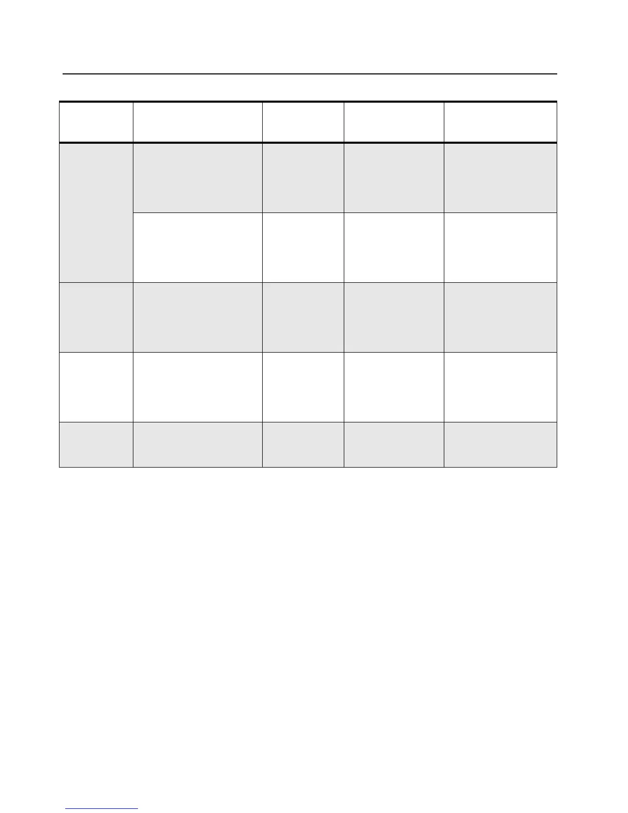
Table 3-5. Receiver Performance Checks
Tes t Na me
Communications
Analyzer
Radio Test Set Comments
 Loading...