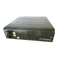
Do you have a question about the Motorola M120 and is the answer not in the manual?
Provides specific details regarding revisions to the instruction manual.
Detailed steps for disassembling the M120 radio, including cover removal.
Procedure for removing the control head and chassis covers.
Instructions for safely removing the RF shield from the radio chassis.
Procedure for removing the RF circuit board from the radio.
Procedure for removing the logic circuit board from the radio.
Procedure for removing the Power Amplifier (PA) circuit board.
Reverse procedure for reassembling the M120 radio unit.
Details the RF board's signal path and component functions.
Describes the VHF receiver front end for the 146-174 MHz range.
Describes the UHF receiver front end for various frequency bands.
Explains the operation of the receiver back end circuits.
Details the frequency synthesizer block diagram and operation.
Describes the function of the logic board and its main components.
Details the microcomputer and its interaction with the logic circuits.
Details the path and processing of audio signals received by the radio.
Describes the path of voice signals through the radio during reception.
Explains the path of data signals within the radio during reception.
Details the audio path for transmitted signals.
Describes the path of voice signals through the radio during transmission.
Explains the path of data signals during transmission.
Details how transmitter power is controlled.
Provides information on RF power amplifiers used in the radio.
Details the 10-watt VHF Power Amplifier, including stages and operation.
Details the 25-45 watt VHF Power Amplifier stages and operation.
| Channels | 16 |
|---|---|
| Power | 5W |
| Bands | VHF |
| Frequency Range | 136-174 MHz |
| Power Output | 5 Watts |


