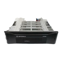


Do you have a question about the Motorola MTR2000 and is the answer not in the manual?
Details Motorola's warranty terms, exclusions, and conditions for radio communications products in the US.
Specifies the manual is for experienced Motorola service technicians for troubleshooting and repair.
Provides contact information and procedures for ordering necessary replacement parts and service tools.
Lists essential service aids and tools required for servicing the MTR2000 station.
Lists specific receiver modules available for the MTR2000 system.
Lists specific transmitter modules used in the MTR2000 system.
Lists the specific station control module used in the MTR2000 system.
Lists the various wireline interface boards available for the MTR2000.
Lists the auxiliary I/O board used in the MTR2000 system.
Lists the backplane module used in the MTR2000 system.
Specifies the receiver module models (TRD6431C/TRD6411C) covered by the diagrams.
Provides schematics for various sections of the receiver module.
Shows the component placement on the receiver board's heavy component side.
Details the specific parts and Motorola part numbers for the TRD6411C receiver module.
Details the specific parts and Motorola part numbers for the TRD6431C receiver module.
Provides a functional block diagram for the TTD6301C exciter module.
Provides schematics for various sections of the TTD6301C exciter module.
Shows the component layout for the TTD6301C exciter module's heavy component side.
Details the specific parts and Motorola part numbers for the TTD6301C Exciter Module.
Provides a functional block diagram for the TTD1921A/TTD1781A 30/40W PA modules.
Provides schematics for various boards within the 30/40W PA module.
Shows the component layout for the PA module boards on heavy and light component sides.
Details the specific parts and Motorola part numbers for the TTD1921A 30W PA module.
Details the specific parts and Motorola part numbers for the TTD1781A 40W PA module.
Provides a functional block diagram for the CLD1301A/CLD1300A 100W PA modules.
Provides schematics for various boards within the 100W PA module.
Shows the component layout for the 100W PA module boards on heavy and light component sides.
Details the specific parts and Motorola part numbers for the CLD1301A 100W PA module.
Details the specific parts and Motorola part numbers for the CLD1300A 100W PA module.
Shows the functional block diagram for the TCN6273N Station Control Module.


