Do you have a question about the Motorola MTS LiTE and is the answer not in the manual?
Compares two software architectures (BR-Arch-1 and BR-Arch-2) for MTS Base Radios, detailing boot order and functionalities.
Describes the MTS platform's functions, versions (LiTE, 2, 4), module configurations, and system infrastructure communication.
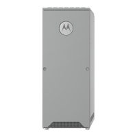
Details the components of the MTS LiTE cabinet, including cabinet material, door, panels, card cage, and modules.
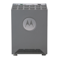
Details the components of the MTS 2 cabinet, including cabinet material, door, panels, card cage, and modules.
Details the components of the MTS 4 cabinet, including cabinet material, door, panel, filter section, and card cages.
Details the components of the Expansion Cabinet, including its structure, junction panel, filter, combiner, card cages, and modules.
Lists the modules that comprise an MTS, including RF Distribution System, RF Filter, Site Controller, XHUB, Base Radio, Power Supply, and Cooling Fans.
Provides essential safety warnings for working with MTS equipment, including electrical, RF energy, and physical hazards.
Highlights safety information related to mains voltage within the MTS power supply module.
Details safety information related to working with or operating MTS batteries, including handling and hazardous gases.
Discusses proper planning to prevent interference, maximize performance, and minimize cabling length.
Provides guidelines for installing MTS equipment cabinets, including dimensions, clearances, and door handling.
Provides guidance on proper antenna placement for the RF system, including RF and GPS antennas.
Details considerations for installing network interfaces like Ethernet, X.21, or E1, including surge arrestor requirements.
Covers special considerations for MTS installation, including electrical access, hazardous materials, and seismic areas.
Discusses environmental factors like temperature, humidity, corrosive environments, and air quality for MTS operation.
Details electrical requirements for MTS installation, including power sources, safety precautions, and applicable codes.
Provides an overview of MTS hardware installation, including cabinet mounting options and access points.
Specifies the personnel required for MTS site installation, including supervisors and engineers.
Outlines the procedure for inspecting MTS equipment upon receipt, including precautions for electrostatic discharge.
Details the necessary steps and planning required before performing MTS installation tasks.
Provides instructions and safety considerations for moving MTS cabinets, including specific guidance for different models.
Covers methods for installing MTS cabinets, including wall fixing or floor fixing, and required clearances.
Guides on connecting various electrical cables after mechanical installation, including grounding and power supply connections.
Details AC power cabling between Junction Panel and Power Supply Unit, and DC power cabling between units within the cabinet.
Provides cabling diagrams and tables for User Alarms/Controls, X.21, RGPS, and GPS connections for MTS LiTE, MTS 2, and MTS 4.
Explains E1 and Ethernet cabling between the Site Controller, Junction Panel, and Base Radios for MTS LiTE, MTS 2, and MTS 4.
Details Ethernet Site Link cabling procedures, including retrofit kits for older Junction Panels and configurations.
Provides RF cabling diagrams and details for various RF configurations of MTS LiTE, MTS 2, and MTS 4.
Explains CAN Bus cabling between Site Controllers, PSUs, DPMs, and ATCCs for MTS LiTE, MTS 2, and MTS 4.
Outlines setup and test procedures for MTS functionality, module failure isolation, and configuration verification.
Details the steps required before proceeding with MTS configuration and testing, including MMI commands and test equipment.
Explains MMI commands for site controller and base radio configuration, covering modes like BOOT1, Test Application, and Base Radio Core.
Lists recommended test equipment for MTS equipment cabinet procedures, including models and usage.
Describes the Service Cable and Connector Box used for MMI commands and sensitivity measurements.
Explains CAN Bus configuration and diagnosis using MMI Commands from the Site Controller for various modules.
Details procedures for verifying Site Controller operation, including configuration, E1/X.21 loopback, and SRI functioning.
Covers procedures for ensuring Base Radio is operational, including BRC state verification and configuration of parameters.
Explains the RFDS module's subcomponents (Preselector, Duplexer, etc.) and its role in distributing and filtering frequencies.
Describes the RFDS for MTS LiTE and MTS 2, including Preselector and Duplexer configurations and specifications.
Details the RFDS for MTS 4, including Preselectors, Post Filters, Duplexers, Hybrid Combiners, and Filter Tray configurations.
Describes the RFDS for the Expansion Cabinet, including RX Splitters and Cavity Combiners.
Explains the Site Controller's role in managing MTS resources, including GPS module functionality and system timing.
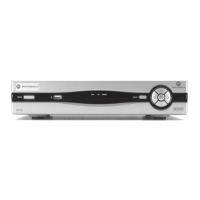
Provides information on the Site Controller's front and rear panel indicators, switches, and connectors.
Describes the CAN Bus communication between RFDS equipment, PSU, and Site Controller, including module addressing.
Covers procedures for checking and replacing the Site Controller's lithium battery, including resetting RTC status.
Explains the XHUB Controller's function as a switching and interface module, and its operating modes.
Details the XHUB Controller's front panel indicators, switches, and connectors for operation and identification.
Provides procedures for replacing the XHUB Controller, including safety precautions and handling instructions.
Provides an overview of the Base Radio, its capabilities, and front panel connectors and indicators.
Explains the Base Radio's subcomponents (Transceiver, Power Amplifier) and its operation within the MTS.
Details the Base Radio's LED indicators, connectors, and their respective functions and indications.
Outlines procedures for replacing the Base Radio module, including safety precautions and step-by-step instructions.
Explains the PSU's theory of operation, including input voltages, output voltages, and compliance standards.
Describes the PSU's LED indicators, their conditions, and corresponding indications for monitoring status.
Details the function of the PSU ON/OFF switch, which disconnects DC outputs and charging currents.
Lists and describes the PSU connectors on the front panel, referring to cabling diagrams for interconnection.
Provides procedures for replacing the PSU, including removal, installation, and mapping list updates.
Describes the cooling fan modules, their sensors for monitoring revolution, and alarm generation upon failure.
Explains how MTS card cages contain fan kits controlled by the Site Controller via CAN Bus based on module temperature.
Provides step-by-step instructions for replacing cooling fans, including safety precautions for unplugging connectors.
Details Site Controller fault indications, LED fault indications, and troubleshooting flowcharts for common issues.
Provides guidance on isolating Base Radio failures and troubleshooting miscellaneous issues like communication and transmission problems.
Declares compliance with EU Directive 2011/65/EU (RoHS-2) and India RoHS regarding hazardous substances.
Presents environmental specifications (humidity, altitude, protection) and standards compliance (Harmonized EN, EU Directives, Safety, EMC).
Includes dimensions for MTS cabinets and technical specifications for modules like frequency range, RF specs, and transmitter/receiver specs.
Describes how to add an additional Base Radio to an MTS 2, including cable connections and configuration.
Explains how to add a second module cage to an MTS 4 cabinet, including cable connections and PSU configuration.
Details how to add a Base Radio into an existing module cage of the MTS 4.
Covers adding a redundant Site Controller to MTS 4, including hardware pre-checks, configuration files, and Ethernet ports.
Explains how to expand from a two-channel Cavity Combiner to a four-channel one, including cable connections and installation.
Describes how to expand an MTS 4 with an additional Hybrid Combiner, including installation procedures.
Details the process of expanding an MTS 2 to an MTS 4 cabinet, including module cage extraction and assembly.
Explains how to add a redundant XHUB Controller to an MTS 4 Expansion Cabinet, including cable connections and configuration.
Lists available FRUs for MTS LiTE, including Site Controller, Base Radios, and Power Supply Units.
Lists available FRUs for MTS 2, including Site Controller, Base Radios, Power Supply Units, and other components.
Lists available FRUs for MTS 4, including Site Controller, Base Radios, and Filter configurations.
Details the three types of surge arrestors (AC Power, Antenna, Lightning) and their recommended suppliers.
Provides precautions for handling static-sensitive boards and modules, including wrist strap usage and environment considerations.
Details safety precautions for using the ESD socket and wrist strap for electrostatic discharge protection.
| Brand | Motorola |
|---|---|
| Model | MTS LiTE |
| Category | Accessories |
| Language | English |