EasyManuals Logo

Motorola MTS LiTE User Manual

Motorola MTS LiTE
480 pages
To Next Page IconTo Next Page
To Previous Page IconTo Previous Page
Page #152 background imageLoading...
Page #152 background image
15
0
6802800U74-AN
Chapter 5: Interconnection and Internal Cabling
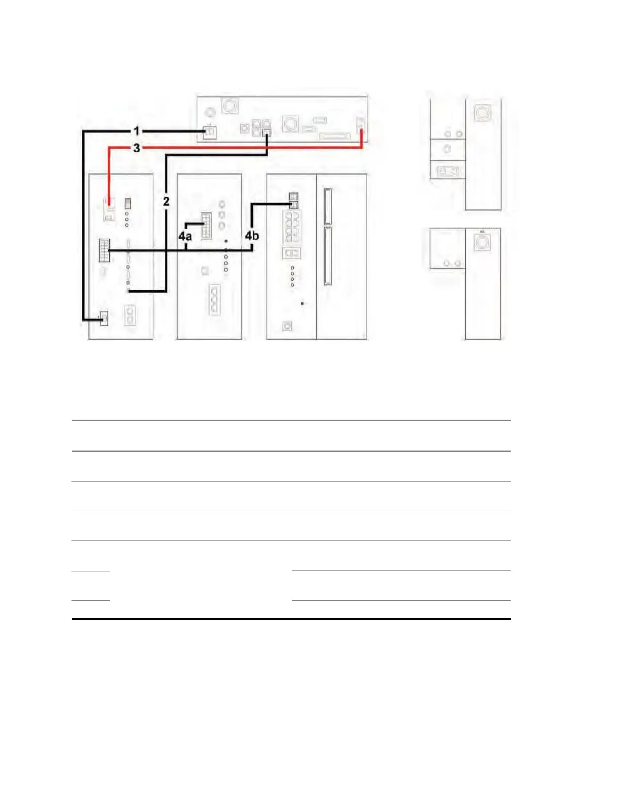
Figure 89: AC/DC Power Cabling Diagram for MTS LiTE
5.1.2
AC/DC Power Cabling – MTS 2
Table 34: AC/DC Power Cabling for MTS 2
In-
dex
Cable Part
Number
From Unit/ Connec-
tion Name
To Unit/ Connection
Name
Notes
1 3066550B01 Junction Panel/ DC
Power Supply Unit/
DCIn Battery
N/A
2
3066556B01
Junction Panel/ Bat-
Temp.
3
3066552B01
Junction Panel/ AC
In
Power Supply Unit/
BatteryTemp.Sens.
Power Supply Unit/
ACIn
N/A
With retaining clip
4a
3066545B01
Junction Panel/ AC
Base Radio 1/ DCIn
Pins: 1, 2, 3, 8, 10,
and 11
Pins: 4, 5, 6, 9, 12,
4b In 2 Base Radio 2/ DCIn
and 13
4c Site Controller/ Power Pins: 7 and 14
JUNCTION PANEL TOP VIEW
FRONT VIEW
GND
DUPLEXER
TOP VIEW
TX/RX
Ant. 2
Ant. 1
LINK 1 LINK 2
X.21
AC in
DC GPS
RGPS
User Alarms/Controls
BR1 BR2
E1 Bat. Temp
Tx
POWER SUPPLY UNIT
FRONT VIEW
BASE RADIO
FRONT VIEW
FRONT VIEW
SITE CONTROLLER
REAR VIEW
CAN 1 CAN 2
POWER SUPPLY
BASE RADIO
SITE CONTROLLER
Power
Power 2
Rx 1
Power 1
AC In
DC in
AC In Status
DC In Status
DC Out / Temp
Rx 2
BR1
BR3
BR4
Rx 3
BR2
CAN
E1
PRESELECTOR
FRONT VIEW TOP VIEW
RX
DC Out.
Reset
Service
Exp. Cab
Fan 1
Status
TX
Red
In
Fan 2
AUX
Red.
Out
BR1 BR2
Tx
Status
Status
BR
Alarm
Fan 3
ATCC
DC Out
Status
Active
Mode
GPS
BTS Alarm
Battery Temp.
Service
Sens.
SC1
DC in
Battery
Reset
SC2
CAN 1
CAN 2
GPS
Alarms/Control
X.21/Remote GPS

Table of Contents

Questions and Answers:

Question and Answer IconNeed help?

Do you have a question about the Motorola MTS LiTE and is the answer not in the manual?

Motorola MTS LiTE Specifications

General IconGeneral
BrandMotorola
ModelMTS LiTE
CategoryAccessories
LanguageEnglish

Related product manuals