6802800U74-AN
Chapter 10: Base Radio
For more information on Base Radio indicators and connectors, see Base Radio – Indicators and
Connectors on page 325 in this chapter.
10.2
Base Radio – Theory of Operation
The Base Radio (BR) provides reliable digital communications capabilities. Each Base Radio contains
the following subcomponents:
• Transceiver consisting of a Base Radio Controller, a triple receiver, and an exciter
• Power Amplifier (PA)
In the MTS 2 and 4, the Base Radio (BR) operates in conjunction with the Site Controller (SC) through
a properly terminated 100Base-T Ethernet link.
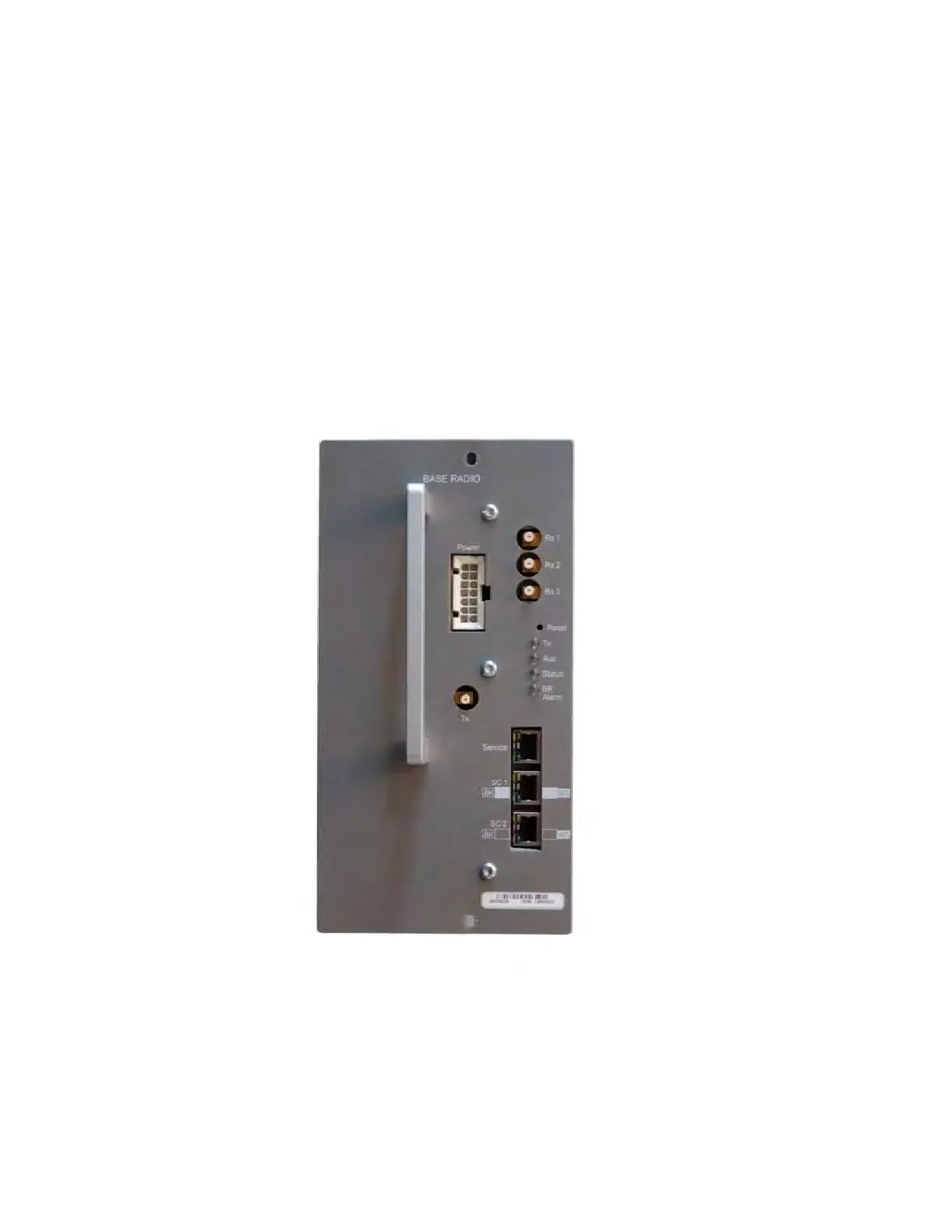
Figure 177: Base Radio Front Panel
On the front panel, there is a DC power input, three parallel receiver (RX) inputs, a high power
transmitter output signal from the power amplifier, a service port, two interfaces to the Site Controllers,
and LED indicators. For more information on the LED indicators, see Table 99: Base Radio – LED
Indicators on page 325.
The following figures show overall block diagrams of the Base Radios for both architectures: BR-
Arch-1 and BR-Arch-2.
 Loading...