EasyManua.ls Logo

Motorola MVME5100 - User Manual

Motorola MVME5100
127 pages
Print Icon
To Next Page IconTo Next Page
Loading...
MVME5100
Single Board Computer
Installation and Use
V5100A/IH5
April 2006 Edition

Table of Contents

Other manuals for Motorola MVME5100

Questions and Answers

  • M
    Marilyn WolfeAug 2, 2025
    Why does my Motorola Desktop have no display and nothing works?
    • K
      Kristi McfarlandAug 2, 2025
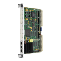
      If nothing is working and there's no display on your Motorola Desktop terminal, it could be due to several reasons. First, check that the system is plugged in and the board is securely installed. Ensure all necessary cables are connected. If the LEDs are lit, the board might be in the wrong slot; the MVME5100 should be in the first (leftmost) slot, and the 'system controller' function should be enabled as per the instructions. Also, the 'system console' terminal may be configured incorrectly, so configure it according to the manual.
  • D
    Debra PetersonAug 6, 2025
    What to do if Motorola Desktop keyboard and mouse not working?
    • L
      Larry MendezAug 7, 2025
      If your Motorola Desktop has a display but the keyboard or mouse aren't working, the problem could be with the connections. Recheck the keyboard and mouse connections, including power, and verify the correct configuration of the RS232 interface. Also, check the board jumpers according to the manual's instructions. You might have accidentally activated flow control by pressing a HOLD or PAUSE key, or by typing -S; if so, press the HOLD or PAUSE key again, or type -Q.
  • B
    billy00Aug 11, 2025
    How to fix Motorola Desktop when Debug prompt PPC6-Bug doesn't appear at powerup?
    • F
      fpooleAug 11, 2025
      If the Debug prompt PPC6-Bug> doesn't appear when you power up your Motorola Desktop and the board doesn't autoboot, it could be due to missing Debugger Flash. To resolve this, disconnect all power from your system, then check that the proper debugger devices are installed. Reconnect the power, and restart the system using the ABT/RST switch (press and hold for 3-5 seconds). If the debug prompt appears, proceed to step IV or V as indicated; otherwise, go to step VI. The board may also need to be reset.
  • B
    Brian BrownAug 15, 2025
    Why Motorola Desktop doesn't autoboot when Debug prompt PPC6-Bug appears?
    • J
      Jose NelsonAug 15, 2025
      If the Debug prompt PPC6-Bug> appears when you power up your Motorola Desktop, but the board doesn't autoboot, the initial debugger environment parameters may be set incorrectly. Start the onboard calendar clock and timer by typing: set mmddyyhhmm , replacing the characters with the month, day, year, hour, and minute. Be cautious, as the next step (env;d) will change some parameters that may affect your system’s operation.
  • S
    Samuel ThompsonAug 25, 2025
    What to do if my Motorola Desktop board failed tests and cannot be corrected?
    • S
      sabrina04Aug 25, 2025
      If your Motorola Desktop board fails one or more tests and cannot be corrected using the provided steps, document the problem and return the board for service. You may also phone 1-800-222-5640.
  • D
    daniel14Aug 28, 2025
    What does it mean if my Motorola Desktop board autoboots and passes self tests?
    • J
      jonessarahAug 28, 2025
      If the debugger is in system mode, the Motorola Desktop board autoboots, or the board has passed self-tests, no further troubleshooting steps are required.
  • J
    Jimmy McmahonNov 18, 2025
    What to do if Motorola Desktop board doesn't autoboot after Debug prompt PPC6-Bug appears?
    • P
      Patrick GutierrezNov 18, 2025
      To resolve the issue of the Debug prompt PPC6-Bug> appearing at powerup but the Motorola Desktop board not autobooting: at the command line prompt, type in: env;d to set up the default parameters for the debugger environment. When prompted to Update Non-Volatile RAM, type in: y . When prompted to Reset Local System, type in: y . After the clock speed is displayed, immediately (within five seconds) press the Return key: or BREAK to exit to the System Menu. Then enter a 3 for 'Go to System Debugger' and Return: 3 . Now the prompt should be: PPC6-Diag>. You may need to use the cnfg command to change clock speed and/or Ethernet Address, and then later return to: env and step 3. Run the selftests by typing in: st . The tests take as much as 10 minutes, depending on RAM size. They are complet...

Summary

Safety Summary

General Safety Precautions

Covers grounding, hazardous atmospheres, internal circuits, CRT handling, component mods, and manual compliance.

About This Manual

Document Structure Overview

Details the manual's chapters, appendices, and their contents.

Conventions and Terminology

Explains typographical conventions and technical terms used throughout the manual.

Hardware Preparation and Installation

Getting Started and Requirements

Information on preparing the system, including unpacking and necessary equipment.

Hardware Configuration and Jumpers

Details on setting jumpers for board configuration and operation modes.

Installation Procedures

Steps for installing PMC modules, PMCspans, and the MVME5100 into a VME chassis.

Operation

Switches, Indicators, and Connectors

Description of front panel switches, LEDs, and I/O connectors.

System Powerup and Initialization

Process of powering up the system and initializing hardware/firmware.

PPCBug Firmware

Overview and Functionality

Introduction to PPCBug, its features, architecture, and usage.

Configuration and Settings

Details on default settings, environment variables, and VMEbus interface configuration.

Pin Assignments

Jumper and Connector Summary

Overview of jumpers and connectors for the MVME5100.

Detailed Pin Assignments

Specific pinout details for various connectors like IPMC761, PMC, VMEbus, Ethernet, COM.

Programming the MVME5100

Memory Maps

Description of memory organization from MPU, PCI, and VMEbus perspectives.

Processor and Bus Mapping Details

Explains processor, PCI, VMEbus, and PCI Local Bus memory maps.

Programming Considerations

Discusses programming practices, PCI arbitration, and interrupt handling.

Thermal Analysis

Thermally Significant Components

Identifies key components and their maximum allowable operating temperatures.

Temperature Measurement Procedures

Methods for measuring component junction, case, and local air temperatures.

Related Documentation

Motorola Publications

Lists referenced Motorola documents for further information.

Manufacturer Documents and Specifications

Lists third-party documents and specifications relevant to the product.

Motorola MVME5100 Specifications

General IconGeneral
BrandMotorola
ModelMVME5100
CategoryMotherboard
LanguageEnglish

Related product manuals