3-8 Radio Disassembly — Detailed
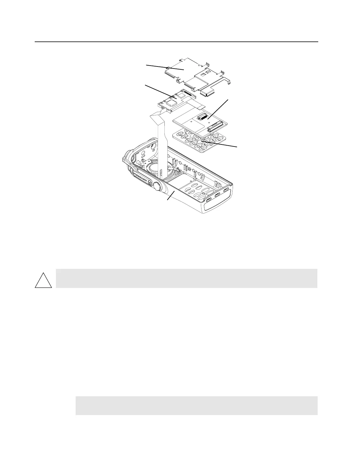
Figure 3-7. Keypad Retainer and Other Boards Removable
3.6.4 Display Disassembly
1. If disassembly involves the removal of the display module, with the keypad retainer removed,
disconnect the display flex from the keypad option board connector by lifting the latch on the
connector.
2. For the PRO7150 and PRO7350, the display module is attached to the front cover with a double-
sided adhesive pad. Carefully pull up on the display module, lifting only at the bottom corners,
remove it from the front cover. Use a new piece of double-sided adhesive to re-mount the display
to the cover.
3. For the PRO9150 only, The display module snaps into the front cover assembly. Insert two flat
blade screwdrivers between the flexible beam at the top of the display module (one on each side).
Deflect the beam down until it moves past the hooks on the front cover. The display module is
hooked to the front cover at the base of the display. Lift the top of the display module past the
hooks and remove from front cover.
3.6.5 Speaker, Microphone, and Universal Connector Flex Disassembly
1. If disassembly of the speaker-microphone assembly is necessary, remove the dustcover by
turning the screw at the bottom of the dustcover counterclockwise with your fingers. Lift the
dustcover out of its pocket.
CAUTION: Take care not to damage the display. Do not cut, bend, or pinch the heat seal.
Display modules contain CMOS devices. Be sure to use ESD protection.
NOTE The dustcover must be removed to remove the speaker-microphone assembly flex
circuit.
Retainer
Display
Module
Keypad
Option
Board
Keypad
Radio
Body

 Loading...