Do you have a question about the Motorola SYNTOR X and is the answer not in the manual?
Manual's purpose for experienced technicians familiar with radio equipment.
How to identify Motorola product model and kit numbers stamped on nameplates.
Motorola's national service organization and authorized service stations.
Procedures for ordering replacement parts and equipment information.
Addresses for sending written orders for parts and equipment.
Phone numbers for ordering parts and service items.
Telex and FAX numbers for ordering parts and service items.
Contact information for customer service and parts identification.
Contact information for national data services.
Precautions for safe use of radio equipment and OSHA limits.
Warnings regarding radio installation and potential hazards.
Warnings for vehicles with anti-skid systems and LPG fuel.
Steps to prevent static discharge damage to CMOS ICs during handling.
Warnings related to using wrist straps and avoiding electrical contact.
List of models and components for Range 1.
List of models and components for Range 2.
List of models and components for Range 3.
List of models and components for Range 4.
List of models and components for Range 5.
List of models and components for Unified Chassis Range 1.
List of models and components for Unified Chassis Range 2.
List of models and components for Unified Chassis Range 3.
List of models and components for Unified Chassis Range 4.
List of models and components for Unified Chassis Range 5.
Specifications for modes, channel resolution, power, dimensions, and weight.
Output impedance, emissions, frequency stability, modulation, and audio sensitivity.
Dimensions, weight, and current drain for control head and speaker.
Input impedance, sensitivity, selectivity, audio output, and FCC designation.
List of optional features for Systems 90S.
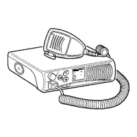
Overview of the UHF SYNTOR X Radio as a microcomputer-controlled transceiver.
Key standard features like TRAKMODE, mode-select, and rugged construction.
How the TRAKMODE system uses a microcomputer and memory module.
Operator control using a mode-select switch for various functions.
Details on the EEPROM memory module for storing parameters.
Radio's ability to operate across wide frequency ranges without degradation.
How the synthesizer generates frequencies electronically.
Improved performance specs for TX/RX over bandwidths.
Direct communication between mobile units via talkaround.
Scanning parameters preprogrammed into the memory module.
Optional preamplifier to improve receiver sensitivity.
Transmitter timer to prevent channel tie-up by limiting transmit duration.
Squelch that unmutes on signal strength and proper code.
Basic radio components and features for a 12-volt system.
Breakdown of the radio into physical blocks like personality board, RF board, etc.
Overview of the radio's four functional parts: microcomputer, synthesizer, receiver, transmitter.
How the microcomputer controls the radio via memory module parameters.
Details on the PLL, VCO, and how frequencies are generated.
How transmit frequency is applied to the transmitter stage.
How modes are preprogrammed with operational data.
Data contained in each mode, like frequencies, codes, and scan settings.
Description of mode labels (A, B, C) and their contents.
Variable duration options for the time-out timer.
Differences in unmuting behavior between squelch types.
How Mode 1 specifies channel scan parameters and priority.
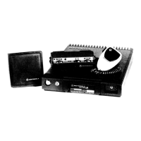
Radio's power requirements and physical housing details.
Radio circuits divided into five removable subassemblies for easy replacement.
Occupies 487 cubic inches, weighs 22.5 lbs (10.2 kg).
Description of controls and indicators on the SYNTOR X control head.
Steps to power on the radio and select modes for receiving.
Steps to power on, key the microphone, and transmit.
How SYNTOR X modes are preprogrammed with user-specified parameters.
List of test equipment and minimum specifications for servicing.
Overview of the five adjustable items on the radio.
Diagram showing adjustment points on the RF board.
Adjusting oscillator frequency, deviation, compensation, and transmitter power.
Warning against readjusting the receiver due to factory pre-adjustment.
Procedure for setting the oscillator frequency using a test set.
Procedure for setting deviation for PL/DPL and non-PL/DPL radios.
Procedure for adjusting compensation for DPL performance and flat response.
Steps to set transmitter power output using a wattmeter.
Procedures for accessing boards and removing the radio.
Steps to remove the common circuits board for servicing.
Steps to remove the personality board from the radio.
Steps for removing the RF board and its associated components.
Procedures to remove the internal casting and its sub-components.
Steps for removing the first mixer and low-pass filter/preamplifier.
Procedures for removing and replacing the VCO assembly and buffer.
Procedures for replacing transistor modules in the power amplifier.
Steps to remove the RF power amplifier and A+ distribution board.
Procedures for removing the front latch and directional coupler.
Steps for removing and troubleshooting the antenna relay.
Table linking symptoms to possible causes and diagnostic diagrams.
Overview of antenna switch function in receive and transmit modes.
Specifies a VOM for checking continuity paths.
Steps for performing receive and transmit signal path tests.
Detailed guide linking symptoms to possible causes and diagnostic diagrams.
Procedure to check radio's power output after installation.
Steps to verify power output against specifications and antenna resonance.
Comprehensive list of mechanical parts with reference symbols and part numbers.
Visual representation of all mechanical parts and their assembly order.
Diagram illustrating the functional blocks and signal flow within the radio.
Detailed diagram showing signal flow between different radio sections.
Further details of signal flow and component interconnections in the block diagram.
Guidelines for handling and soldering ceramic microstrip modules.
Procedures and warnings for removing and replacing chip capacitors.
Steps for replacing power transistors, including thermal compound application.
Illustrations showing techniques for removing chip capacitors.