2
Connect a new or known good PSSM to the radio, which must
have an RF adapter attached. Transmit to the equipment using
the microphone’s PTT by radiating to an input antenna on the
equipment at a distance that causes a mid-scale result. For a
receiver set for threshold squelch, set the squelch to just open
when transmitting. Next, connect the PSSM to be tested to
the radio, and transmit at the same distance as above. The
result should compare closely to the known good or new
microphone for field intensity.
III. HANDLING PRECAUTIONS
To avoid damage to circuits, observe the following handling,
shipping, and servicing precautions.
I. If the PSSM has been exposed to water, turn the unit so
that the speaker grille faces the ground and tap the unit
against your palm to remove any residual water. Blow out
any residual water from the microphone grille area before
operating the radio; otherwise, the sound may be
distorted until the water has evaporated from these areas.
J. For proper RF performance, avoid damage to, or
contamination of, the PSSM’s RF interface connector and
surrounding environmental seal. The RF interface
connector is located near the end of the curved arm that
protrudes from the top of the PSSM housing, and is the
portion that mates with the RF adapter on a properly
equipped radio.
IV. MAINTENANCE
Refer to the schematic diagram, the exploded view, and the
parts lists. Every part in the microphone is identified and
illustrated for assistance in removal and replacement.
If disassembly of the PSSM is required, do not reassemble it
without doing the following (numbers in parentheses refer to
item numbers in the exploded view).
• Remove the O-ring gasket (22) from the cover assembly
(16).
• Inspect the seal areas around the housing (1) and the
cover (16) for foreign material which might prevent the
O-ring gasket from sealing properly.
• Inspect O-ring gasket (22) and both cover screw O-ring
gaskets (18). If any of these are split, cracked, or damaged
in any way, discard and replace them.
• If the main printed circuit board (14) is removed, remove
the speaker spacer (27) and inspect the membrane of the
seal pad (28) for tears or holes. If the membrane is
damaged, remove it, being careful to remove all old
adhesive, and replace it with a new seal pad.
NOTE
When placing the seal pad (28), it is critical that
the small seal pad opening be aligned with the
microphone port in the housing.
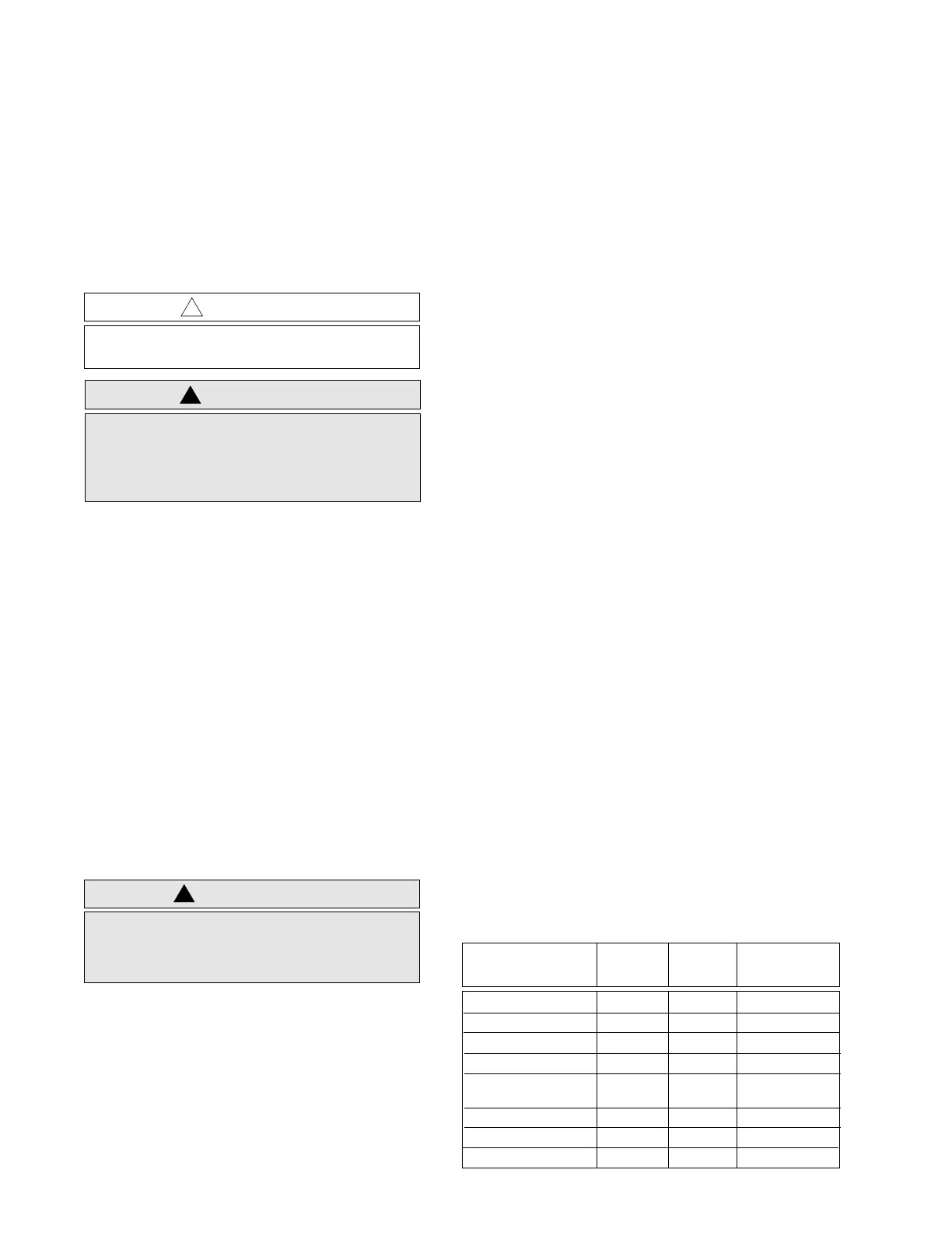
• Tighten all hardware loosened or removed during
disassembly per the values listed in the Torque
Specifications table. Use the recommended torque driver
(RSX-4043A Rototorq Tool or equivalent).
If necessary, the external surfaces of the remote speaker
microphone may be cleaned with 0.5% solution of mild
dishwashing detergent in water (one teaspoon of detergent in
a gallon of water).
A. Prior to and while servicing a PSSM, particularly after
moving within the service area, momentarily place both
hands on a bare metal, earth-grounded surface. This will
discharge any static charge your body may have
accumulated.
B. Whenever possible, avoid touching any electrically
conductive part of the unit with your hands.
C. Because they contribute to static buildup, avoid carpeted
areas, dry environments, and certain types of clothing
(silk, nylon, etc.) when servicing a unit.
D. All electrically powered test equipment should be
grounded. Apply the ground lead from the test
equipment to the unit before connecting the test probe.
Similarly, disconnect the test probe prior to removing the
ground lead.
E. If the microphone cartridge is removed from the unit,
place it on a conductive surface, such as a sheet of
aluminum foil which is connected to ground through
100k ohms of resistance.
F. When soldering, be sure the soldering iron is grounded.
G. Prior to replacing circuit components or touching the
microphone cartridge, be sure to discharge any static
buildup. Since voltage differences can exist across the
human body, it is recommended that only one hand be
used if it is necessary to touch the microphone cartridge
and associated wiring.
H. Replacement microphone cartridges should be kept in
conductive packaging until they are placed in the unit.
Torque Torque Torque
Application (In. Lbs.) (N•m) Bit No.
Cover Screws 6 0.68 6680321B78
PC Board Screws 3 0.34 6680321B78
Clip Screws 4 0.45 6680321B78
Toggle Switch Boot 3 0.34 6680370B99
Connector Assembly 3 0.34 6680381B69
Screw
Ear jack Spanner 3 0.34 6680370B89
Antenna Spanner 20 1.13 6680370B90
Retaining Nut 7 .079 6680370B90
 Loading...