Do you have a question about the Motorola XTS 3000 and is the answer not in the manual?
Details on multi-station reconditioning chargers and their function in extending battery life.
Explains the 4-hour charging time for batteries and the meaning of indicator lights.
Recommendations for placing the radio charger in secure locations.
Covers Ni-Cad/NiMH battery types, expected life, and 'memory' effects.
Explains why the battery is large, relating it to power and operational duration.
Identifies and explains the function of the radio battery's front and rear contacts.
Details on the release button and top lip for securing the battery to the radio.
Describes the D-ring's purpose, attachment to belt holders, and removal process.
Step-by-step guide on how to correctly connect the battery to the radio.
Information on the external ear-phone jack and its required accessories.
Guidance on securely attaching the antenna for proper radio function.
Details on the Emergency Trigger and Repeat/Direct Selector Switch.
Explains the function of the channel selector and volume control knobs.
Covers the Push-to-Talk button, Keypad Lock, and Audio Level Monitor button.
Details on the Scan/Nuisance Delete button and Lighted Display features.
Describes the radio's self-test procedure and error display meanings.
How to identify a low battery condition from the display indicator.
Explanation of the default screen, second line area indicators, and bottom line functions.
Overview of the 6-key keypad and its relation to display functions.
Procedure for changing the radio's operating mode using keypad and arrow keys.
Instructions on how to select different channels using the channel knob.
Details on the structure and content of the new dispatch channel plan.
Details on community college, Clemars, LAPD, and LA County Fire Department channels.
Highlights FCC regulations and penalties for using unlicensed frequencies.
Explains the inclusion of outside frequencies for interoperability purposes.
Conditions for using other police frequencies, including emergencies and agreements.
Procedure for enabling and disabling the scan function via keypad.
How priority scan works with default channels and traffic monitoring.
Steps to program new channels into the scan list.
Procedure for deleting channels from the active scan list.
Discusses the effects of scanning more channels on listening and battery consumption.
Instructions on how to view the programmed scan frequencies on the display.
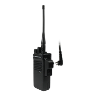
The Motorola XTS 3000 is a rugged, handheld radio designed for professional use, particularly by law enforcement agencies like the Los Angeles County Sheriff's Department. It represents Motorola's "Astro" radio technology, housed in a durable package built to military specifications. This radio is designed for reliability, with very low complete or partial failure rates and comes with a three-year service plan.
The primary function of the XTS 3000 is two-way radio communication, operating within the 450 MHz to 512 MHz frequency range, which allows for broad interoperability with 95% of law enforcement agencies in the Los Angeles area. All its functions and frequencies are software programmable, offering flexibility in its operation.
The radio features an Emergency Trigger, an orange button located in front of the antenna. When depressed for approximately two seconds, it switches the radio to the Emergency Channel in repeat mode and automatically notifies the Sheriff's Communication Center (SCC) of its activation. It does not provide an "open mike," requiring the use of a Push-to-Talk (PTT) switch for transmission. Each time the PTT is depressed in emergency mode, the radio transmits a 5-digit AID number (engraved on the bottom front of the radio), which is heard as a short digital burst. This burst can cover any other radio transmission, emphasizing the importance of not "rushing" the mike. To reset the E-trigger, the radio must be turned off and back on.
A Repeat/Direct Selector Switch allows the user to toggle between repeat and direct (talk around) modes. This collar switch rotates at the base of the middle (frequency) knob, controlling an indicator that moves between a "circle" (direct mode) and a "slash/circle" (repeat mode) on the top/front of the radio. A symbol "I---->I" on the top line of the digital display indicates direct mode. It is important to note that transmitting in direct mode on repeated Dispatch Channels is considered unsafe and a violation of policy, as direct transmissions can interfere with repeated transmissions within a certain range.
The radio includes a Scan function that allows it to monitor multiple selected channels. Users can turn the scan function on or off using the keypad. The radio scans frequencies with different priorities, with the default channel (the one configured by the Mode and Channel knob) being the Priority Scan channel. If there is simultaneous traffic on a scanned channel and the default channel, the user will hear the traffic on the default channel. If no traffic is on the default channel but there is traffic on a scanned channel, the user will hear the scanned channel's traffic. If a microphone is keyed on the default channel while listening to a scanned channel, the radio will return to and transmit on the default channel.
The XTS 3000 is designed for ease of use with several controls:
The radio features a Lighted Display with an automatic backlight that activates for approximately five seconds when channels are changed or the keypad is used.
The Display Screen provides important information:
To change the radio's mode, the user presses the key below "ZONE," then uses the arrow keys until the desired mode flashes. Pressing the HOME key then selects the mode. To change channels, the user turns the channel knob clockwise or counter-clockwise until the desired channel number aligns with the indicator. The channel name will appear on the display.
The new channel plan for each dispatch mode includes Dispatch, L-TAC, A-TAC, etc. The last four channels of each mode are C-TAC channels 1 and 2, the Mutual Aid channel for the area, and the SCC Access Channel.
Mode 8 includes Community College, Clemars, LAPD Access, and L.A. County Fire Department channels. Fire Department channels are restricted to extreme emergencies. Fire Department "Blue" channels are geographic tactical channels (e.g., FIRE BL 1 & 2 for central basin, FIRE BL 3 for west County). While the radio can access these frequencies, unauthorized use carries severe penalties, including fines and loss of frequency licenses. Interoperability is a major concern, and these frequencies are included for emergency situations or when signed frequency sharing agreements exist. LAPD has specifically requested that users not transmit on their dispatch channels.
Users can add or remove channels from the scan function. To add a channel, press the key below "PROG," then "SCAN." The radio enters program mode, indicated by a flashing box. Use arrow keys to change modes and the channel selector knob to select a channel. "SEL" (select) or "DEL" (delete) will appear, and pressing a key will either select or delete the channel. A "Z" symbol indicates a selected scan channel. The Emergency Channel should be programmed as a scanned channel in all radios, but adding or removing it from scan has no effect on the emergency trigger. If no channels are programmed, the radio will display "EMPTY LIST" and emit an 'error' tone when scanning is attempted. More scanned channels consume more battery power.
The XTS 3000 utilizes Ni-Cad or Nickel-Metal Hydride batteries, which Motorola claims have a 10-12 hour life but are still prone to "memory" buildup. If a battery doesn't hold a full charge, it should be returned to the Systems Maintenance Section at SCC for replacement or reconditioning. Typical battery life cycles are 12-18 months.
Multi-Station re-conditioning chargers are provided (one for every seven radios) and are specifically designed for XTS batteries. These chargers reduce memory effect and extend battery life. Batteries charge for four hours; even if a green light appears earlier, they should be charged for the full duration. Trickle-charging occurs after full charge, and extended time in the charger will not damage the batteries. Chargers should be placed in secure locations like a W/Sergeant's, W/Commander's Office, or a locked armory.
The battery is large to provide sufficient energy for a 5-watt portable radio, contributing to longer battery life per shift. The battery has four small round brass plates on the back that are "short-out" protected. However, the three small slots on the front, with visible brass contacts protected by a plastic grid, are the radio contacts and are not short-out protected; contact with metal objects will damage them.
A small button at the bottom of the battery, when pushed, raises two metal clips, releasing the battery from the radio. To connect, the battery's thin plastic lip fits into a groove at the top of the radio, then the battery is lowered and squeezed until it clicks into place.
A "D" button, which fits into the standard Department belt-loop holder, is issued for each battery. It slides into two parallel slots near the top of the battery back. To remove it, push a small metal tab on the plastic lip towards the D-ring while pushing up on the D-ring. When attaching, the D-ring slides into the holder upside down, then pivots right side up, ensuring it pivots freely.
The speaker/microphone head and Push-to-Talk button are of a standard design and are less expensive than previous models. The Department can also make certain repairs. There is no E-trigger on the microphone. The speaker microphone is a permanent part of the radio and should not be removed, as per Department Policy and Station Order.
A small rubber plug on the Mic connector covers the threaded ear-phone jack. This requires a special earpiece from Motorola, with various models available. The rubber plug should be kept inserted when not in use.
The antenna threads and radio threads are metal. The antenna must be firmly tightened for the radio to function properly.
| Signaling | MDC1200, DTMF, Quick Call II |
|---|---|
| Frequency Range | 136-174 MHz, 403-470 MHz |
| Battery Life | Up to 10 hours (depending on usage) |
| Weight | 14.5 oz (411 g) with battery |
| Display | Alphanumeric |
| Zones | 16 |
| Battery Type | NiMH |
| Operating Temperature | -22°F to +140°F (-30°C to +60°C) |
| Water Resistance | IP54 (splash resistant) |