Home
Motorola
Radio
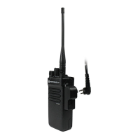
XPR 4300
Motorola XPR 4300 - User Manual
45 pages
Manual
Specs
Ask a question
Save Page as PDF
To Next Page
To Next Page
Loading...
i
zTitle Page
XPR 4300/4350/4500/4550
Mobile Radio
Installation Manual
Motorola, Inc.
8000 We
st Sunrise Boulevard
Fort Lauderdale, Florida
33322
6816812H01
2
Table of Contents
Main Page
default chapter
2
Computer Software Copyrights
2
Disclaimer
2
Document Copyrights
2
Foreword
2
Parts Ordering
2
Trademarks
2
Installation Requirements for Compliance with Radio Frequency (RF) Energy Exposure Safety Standards
3
Table of Contents
5
Mobile Radio Model Numbering Scheme
8
Commercial Warranty
9
General Provisions
9
Limited Warranty
9
Motorola Communication Products
9
What this Warranty Covers and for How Long
9
How to Get Warranty Service
10
State Law Rights
10
What this Warranty Does Not Cover
10
Governing Law
11
Patent and Software Provisions
11
Chapter 1 Introduction
13
Mobile Radio Description
13
Dimensions
13
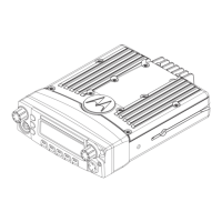
Dash Mount Configuration
14
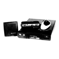
Base/Control Stations
14
Figure 1-3. Dash Mount Configuration
14
Figure 1-4. Remote Mount Configuration, with 110W Transceiver
14
Tools Required for XPR 4300/4350/4500/4550 Installations
15
Chapter 2 Standard Configurations
17
Planning the Installation
17
Figure 2-1. Mounting Flexibility in Middle Console
17
Figure 2-2. on Top or under Dash Mounting
17
Figure 2-3. Radio Installation (Dash Mount) with Transceiver
18
Figure 2-4. Pin Configuration
19
Radio Mounting
20
Figure 2-5. Trunnion Orientation
20
Figure 2-6. Transmission Hump Trunnion Mounting
21
Figure 2-7. below Dash Trunnion Mounting
21
Locking Kit (Optional)
22
All Radios
22
Power Cable
22
Figure 2-8. Locking Kit (Optional) 110W Radios
22
Ignition Sense Cable
24
Antenna Installation
24
Selecting an Antenna Site/Location on a Metal Body Vehicle
24
Mini-UHF Connection
25
Figure 2-30. Mini-UHF Connection (as Shown on MID-Power)
25
Speaker
26
Figure 2-31. Mini-UHF Connector Tool (as Shown on MID-Power)
26
Figure 2-32. Speaker Mounting
27
Microphone Hang-Up Clip
28
Standard Hang-Up Clip
28
Handheld Hang-Up Box
28
Completing the Installation
28
Chapter 3 Options and Accessories Installation
29
Emergency Pushbutton, Footswitch, Horn Relay, and Light Relay Installation
29
Emergency Pushbutton or Footswitch Installation
29
Horn (External Alarm) Relay Installation
29
Lights (External Alarm) Relay Installation
29
Dash-Mount Accessory Installation
29
Figure 3-1. VIP Connector Detail
29
MDC Emergency Pushbutton or Footswitch Installation
30
Figure 3-2. Emergency Switch Wiring Diagram
30
Horn and Lights (External Alarm) Relay
31
Figure 3-3. Horn/Light Wiring Diagram
31
Table 3-1. Rear Accessory Jack Pin Functions
32
Appendix A Replacement Parts Ordering
33
Basic Ordering Information
33
Motorola Online
33
Mail Orders
33
Fax Orders
34
Parts Identification
34
Product Customer Service
34
Glossary
35
Index
43
Need help?
Do you have a question about the Motorola XPR 4300 and is the answer not in the manual?
Ask a question
Motorola XPR 4300 Specifications
Print Specification
General
Number of Channels
32
Operating Temperature
-30°C to +60°C
Bluetooth
No
Frequency Range
136-174 MHz, 403-470 MHz
Signaling
DTMF
GPS
Optional
Related product manuals
Motorola XPR 3000 Series
44 pages
Motorola XTL 1500
120 pages
Motorola XTL 5000
12 pages
Motorola SYNTOR X
42 pages
Motorola XTS 3000
12 pages
Motorola Syntor X9000
80 pages
Motorola Astro XTL 5000
158 pages
Motorola ASTRO XTL 2500
161 pages
Motorola Astro XTL 1500
452 pages
Motorola ASTRO XTS 3000
236 pages
Motorola MOTOTRBO XiR M3688
440 pages
Motorola ASTRO Digital XTL 5000
38 pages