March 23, 2006 6816812H01
2-6 Standard Configurations: Power Cable
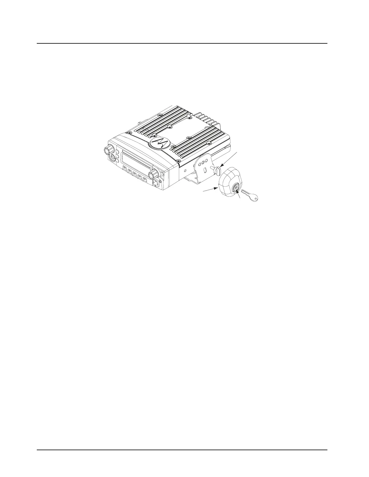
2.2.2 Locking Kit (Optional)
2.2.2.1 All Radios
If an optional locking kit is used (shown in Figure 2-8), position the lock bottom housing on the
trunnion before installing the radio mounting screws. Then slip the top lock housing on and remove
the key. You can install the lock on either side of the radio, and by rotating it 180°, you can also install
it on dash installations.
Figure 2-8. Locking Kit (Optional) 110W Radios
2.3 Power Cable
Route the red radio power cable from the radio to the vehicle’s battery compartment, using accepted
industry methods and standards. Be sure to grommet the firewall hole to protect the cable. Remove
the 15-amp (part number 6580283E06), 20-amp (part number 6580283E07) or 30-amp (for 110W)
fuse from the fuseholder and connect the red lead of the radio power cable to the positive battery
terminal using the hardware provided as shown in Figure 2-9. Connect the black lead to a
convenient solid chassis ground point. DO NOT connect the black lead directly to the battery’s
negative terminal.
Existing
Mounting
Screw
Lock
Lock
Housing
RLN4779_ Locking Kit
 Loading...