March 23, 2006 6816812H01
1-2 Introduction: Standard Configurations
1.2 Standard Configurations
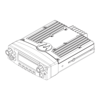
1.2.1 Dash Mount Configuration
In the dash mounting version of the XPR 4300/4350/4500/4550, the control head is mounted on the
front of the transceiver housing. Electrical connection between the two takes place within the radio
via a flexible circuit board between the connectors on the front of the transceiver and at the back of
the control head.
Figure 1-3. Dash Mount Configuration
For details on this configuration, see Section 2.2.1 on page 2-5.
NOTE:
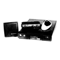
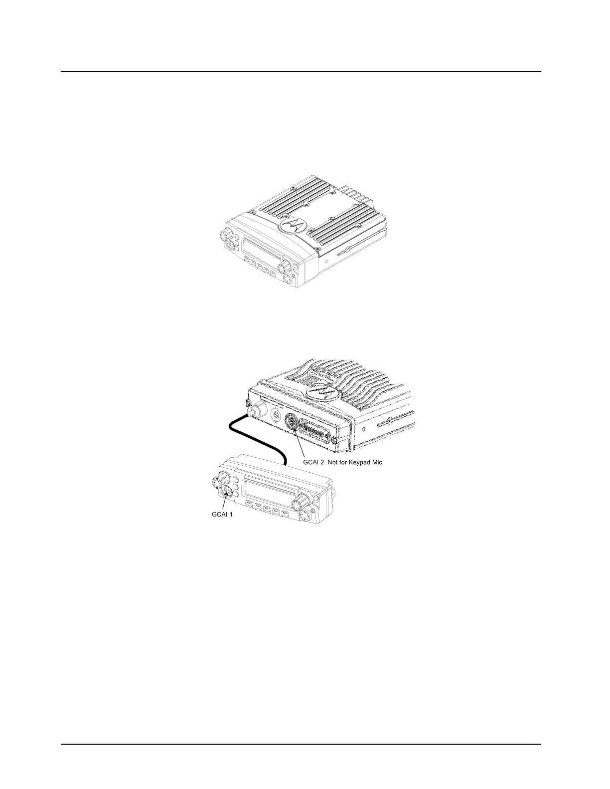
Figure 1-4. Remote Mount Configuration, with 110W transceiver
For details on these configurations, see Section 2.2.2 on page 2-8.
1.3 Base/Control Stations
If mobile radio equipment is installed at a fixed location and operated as a control station or as a
fixed unit, the antenna installation must comply with the following requirements in order to ensure
optimal performance and compliance with the RF energy exposure limits in the standards and
guidelines listed in the 68P81095C99 manual:
• The antenna should be mounted outside the building on the roof or a tower if at all possible.
• As with all fixed site antenna installations, it is the responsibility of the licensee to manage the
site in accordance with applicable regulatory requirements and may require additional compli-
ance actions such as site survey measurements, signage, and site access restrictions in order
to ensure that exposure limits are not exceeded.
 Loading...