March 23, 2006 6816812H01
2-8 Standard Configurations: Ignition Sense Cable
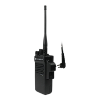
2.4 Ignition Sense Cable
Motorola supplies an ignition sense cable and recommends that it be used with every mobile
installation. The ignition sense cable allows the radio to be turned on and off with the vehicle ignition
switch, and allows the radio to “remember” the state of the radio on/off switch, even if it is changed
while the vehicle is off.
• For radio ON/OFF control independent of the ignition switch, connect the red ignition cable (yel-
low for remote) (pin 25 of accessory connector) to “battery hot” at the vehicle fuse block (dash
mount only).
• For radio ON/OFF control via the ignition switch, connect the red ignition cable (yellow for
remote) to “ignition” at the fuse block.
Note that for remote mount installations, the red and yellow leads are connected, not the red lead
from the rear of the radio.
The ignition sense cable uses either a 3-amp (P/N 6580283E01) or 4-amp (P/N 6580283E02) fuse.
For other considerations when connecting the ignition cable, see the Basic Service Manual
(Motorola publication part number 6881096C73).
2.5 Antenna Installation
IMPORTANT NOTE: To assure optimum performance and compliance with RF Energy Safety
standards, these antenna installation guidelines and instructions are
limited to metal-body vehicles with appropriate ground planes and take
into account the potential exposure of back seat passengers and
bystanders outside the vehicle.
NOTE: For mobile radios with rated power of 7 watts or less, the only installation restrictions are to
use only Motorola approved antennas and install the antenna externally on metal body
vehicles. For mobile radios with rated power greater than 7 Watts, always adhere to all the
guidelines and restrictions in section 2.5.1 below.
2.5.1 Selecting an Antenna Site/Location on a Metal Body Vehicle
1. External installation – Check the requirements of the antenna supplier and install the
vehicle antenna external to a metal body vehicle in accordance with those requirements.
2. Roof top – For optimum performance and compliance with RF Energy Safety standards,
mount the antenna in the center area of the roof.
3. Trunk lid – On some vehicles with clearly defined, flat trunk lids, the antennas of some radio
models (see restrictions below) can also be mounted on the center area of the trunk lid. For
vehicles without clearly defined, flat trunk lids (such as hatchback autos, sport uitility vehicles,
and pick-up trucks), mount the antenna in the center area of the roof.
Before installing an antenna on the trunk lid,
- Be sure that the distance from the antenna location on the trunk lid will be at least 85 cm
(33 inches) from the front surface of the rear seat-back to assure compliance with RF
Energy Safety standards.
- Ensure that the trunk lid is grounded by connecting grounding straps between the trunk lid
and the vehicle chassis.
IF THESE CONDITIONS CANNOT BE SATISFIED, THEN MOUNT THE ANTENNA ON
THE ROOF TOP!
 Loading...