6816812H01 March 23, 2006
Standard Configurations: Power Cable 2-7
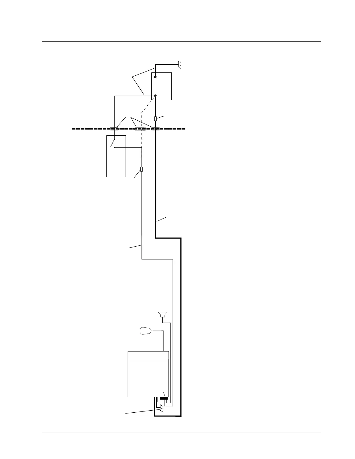
RADIO COMPARTMENT = OPERATOR COMPARTMENT
VEHICLE BATTERY
COMPARTMENT
A good chassis connection via the black primary
power cable is essential for radio operation and
to prevent damage to the radio and cable kit.
Connection to the vehicle frame is desirable.
VEHICLE
BATTERY
15A OR 20A
FUSE
PART OF
VEHICLE
WIRING
VEHICLE
IGNITION SWITCH
ON/ACC
GROMMET
RADIO POWER CABLE
(RED/BATTERY HOT)
RADIO IGNITION
CABLE (thin RED)
SPEAKER
3A OR 4A FUSE
MICROPHONE
RADIO POWER CABLE (BLK/GROUND)
RADIO
(-)
(+)
CAUTION
MAEPF-27646-O
Rear connector
CH
SEE NOTE
NOTE:
Caution: if you choose to connect the radio’s IGNITION line directly to the car’s battery, excess use of the radio when the car’s ignition is not running (i.e. alternator running)
could result in a slow discharge of the car’s battery. This configuration allows the radio to operate with the car’s ignition switch ON or OFF.
If the radio’s IGNITION line is wired to the car’s ignition switch, the radio will only function when the car’s ignition switch is turned ON.
Figure 2-9. Cabling Interconnect Diagram for Dash Mount
 Loading...