Chapter 3 Options and Accessories Installation
3.1 Emergency Pushbutton, Footswitch, Horn Relay, and Light Relay
Installation
Perform the following installation procedure:
1. Select an appropriate place to mount the option or accessory hardware.
2. Route the accessory-to-control head cables under floor coverings or behind panels so that
the vehicle occupants do not snag or break the wires.
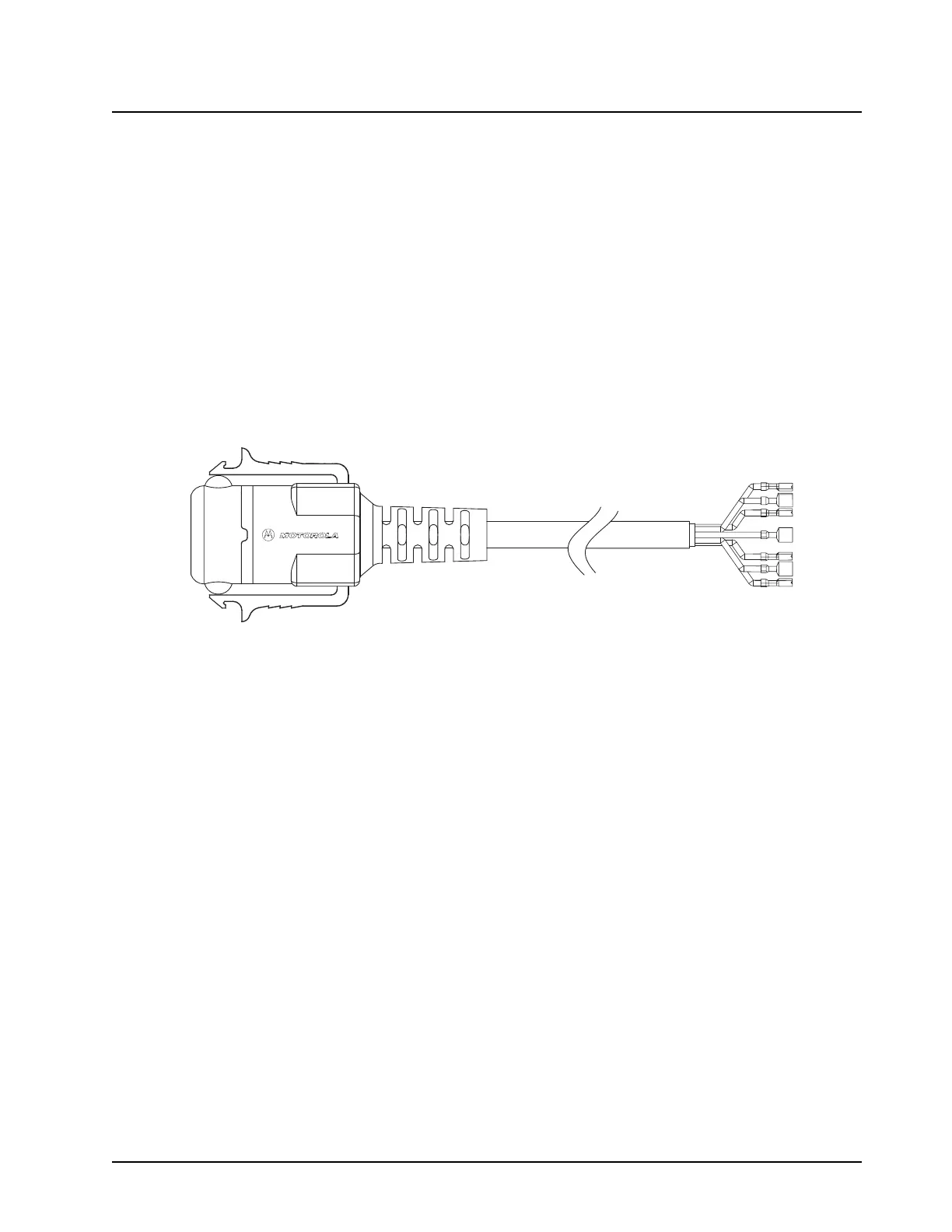
3. Attach wires from the accessory to the appropriate wire on the VIP cable. (see Table 3-1 and
Table 3-2). Figure 3-1 shows how wires are plugged into the connector and how to use an
extraction tool to remove wires.
Figure 3-1. VIP Connector Detail
3.1.1 Emergency Pushbutton or Footswitch Installation
Mount the switch using the hardware that comes with the kit. Connect the emergency switch wires to
a ground pin and a VIP IN pin on the VIP connector.
3.1.2 Horn (External Alarm) Relay Installation
Mount the horn relay in a suitable location (normally under the dash). Connect the relay contacts
across the horn ring switch, typically found in the steering column. Connect the two control wires to a
SW B+ pin and a VIP OUT pin on the VIP connector.
3.1.3 Lights (External Alarm) Relay Installation
Mount the light relay in a suitable location (normally under the dash). Connect the relay contacts
across the headlamp ON/OFF switch. Connect the two control wires to a SW B+ pin and a VIP OUT
pin on the VIP connector.
3.2 Dash-Mount Accessory Installation
For dash-mounted configurations, the accessories must be installed through the accessory
connector assembly that is located on the rear of the radio, adjacent to the power connector.
Motorola-approved accessories are supplied with male terminals crimped to a 20-gauge wire
specifically designed to fit the plug of the accessory connector assembly.
 Loading...