MC70001c_de.doc / Nov-15 Page 7 / 14
1 2 3 4 5 6 7 8 9 10 11 12 13 14 15 16 17
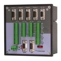
Analogeingänge, Klemmleiste “Ana. IN”
Analogue inputs, terminal strip “Ana. IN”
1 V
10 V
20 mA
GND
1 V
10 V
20 mA
GND
1 V
10 V
20 mA
GND
1 V
10 V
20 mA
GND
GND
Input 1 Input 2 Input 3 Input 4
Analogue IN 1 - Analogue IN 4
1V
10k
10V
OP
20mA
100k
50R
GND
1V
10k
10V
OP
20mA
100k
50R
GND
+
-
20 mA
Stromeingang
Spannungseingang
0V
+/-10V
+/-1V
Voltage input
Current input
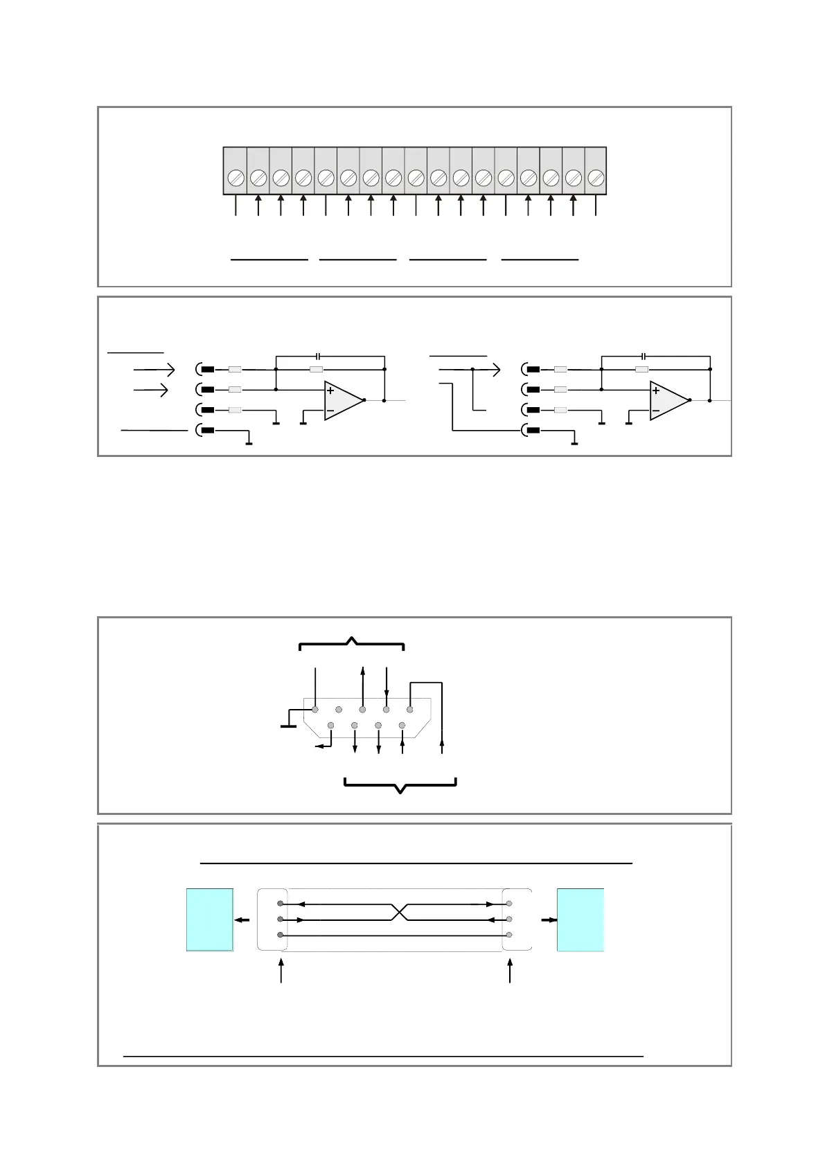
3.8 Die serielle Schnittstelle
Es steht sowohl eine RS232- als auch eine
RS485-Schnittstelle zur Verfügung, jedoch kann
nicht gleichzeitig über beide Schnittstellen mit
dem Gerät kommuniziert werden.
Alle Schnittstellenanschlüsse sind auf der mit
„Serial“ bezeichneten, 9-poligen SUB-D-Buchse
herausgeführt.
The unit provides both, a RS232 and a RS485
interface. However, one of the two can only
communicate with the unit at a time.
All interface lines are accessible by a 9-position
SUB-D-connector (female), marked “Serial”.
12345
6789
+5V out
T+ T- R+ R-
TxD
RxD
RS 232
RS 485
GND
int.
GND
SUB-D-9
(Buchse am Gerät)
(female on unit site)
RxD
TxD
2
3
5
2
3
5
GND
PC
RxD
TxD
MC700
Anschluss eines PC an die RS232-Schnittstelle des MC700-Controllers
How to connect a PC to the RS232 interface of the MC700 controller
Buchse am Verbindungskabel Stift am Verbindungskabel
SUB-D-9 female on the cable site SUB-D-9 male on the cable site
Schirm auf Steckergehäuse
Screen to housing of connector
W ichtig: Für RS232-Betrieb bitte nur die Stifte 2, 3 und 5 anschliessen und alle anderen Stifte frei lassen !
Important: With RS232 operation, please connect only pins 2, 3 and 5 and leave all other pins unconnected !
 Loading...