MC70001c_de.doc / Nov-15 Page 8 / 14
120 Ohm120 Ohm
Schirm
T+
T-
8 7
MC700
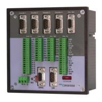
Anschluss der RS485-Schnittstelle im 2-Draht-Verfahren
Use of the RS485 interface with 2-wire mode
Erster Busteilnehmer
First bus participiant
Letzter Busteilnehmer
Last bus participiant
Screen
120 Ohm120 Ohm
Schirm
T+ T- R+ R-
R+ R- T+ T-
6 1 8 7
2 x 2 x
R+ R- T+ T-
MC700
Anschluss der RS485-Schnittstelle im 4-Draht-Verfahren
Use of the RS485 interface with 4-wire mode
Screen
Busmaster
Letzter Busteilnehmer
Last bus participiant
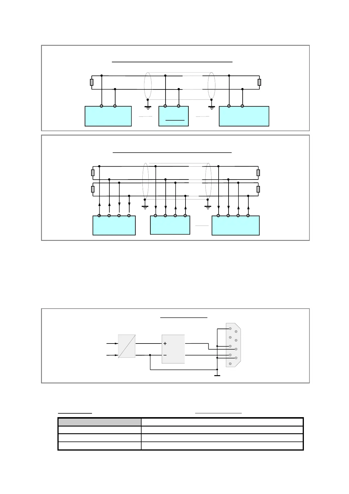
3.9 Das CANopen-Interface
Der Regler ist serienmässig mit einer CANBUS-
Schnittstelle gemäss DIN ISO 11898 (CANopen
CiA DS301) ausgerüstet. Der Bus-Anschluss
erfolgt über den mit „CAN“ bezeichneten, 9-
poligen SUB-D-Stecker (Stift am Gerät).
Der CAN-Bus ist über DC/DC-Wandler
potentialgetrennt.
3.9 The CANopen interface
MC700 controller provides a CAN network
interface according to the DIN ISO 11898
standard (CANopen CiA DS301). The network
connector is SUB-D-9 (male on unit site) and is
marked with “CAN”. Network lines are potential-
separated from other potential by DC/DC
converter.
CAN - BUS Interface
GND1
VCC1
1
2
3
4
5
6
7
8
9
CAN LO
CAN HI
82C150
VCC
GND
DC
DC
CAN
Driver
SUB-D-9
(Stift)
(male)
Zur Verdrahtung des CAN-Busses wer-
den in Abhängigkeit der Leitungslänge
folgende Kabel empfohlen:
The following cabels are recommended
for CAN communication, depending on
the cable length:
LIYCY 2 x 2 x 0,5 mm² (twisted and screened)
 Loading...