9
ENGLISH
EN
4. Pull out the cotter pin and disMantle the steer-
ing wheel jacket.
5. Install the washer/washers in accordance with
point 3 above.
6. Install the steering column jacket on the steer-
ing column and secure by knocking in the cotter
pin fully. Use a counterhold.
3.6 TOWING HITCH
Screw the towing hitch (5:A) into the two holes on
the underside of the rear axle using screws 5:B).
Tighten the screws properly.
Tightening torque: 22 Nm.
3.7 Deck mount
This only describes installation on the right-hand
axle. The same procedure must be carried out on
the left-hand axle.
1. Remove the circlip (17:M) and the outer washer
(17:N).
2. Install the deck mount (17:O).
The washer (17:N) with an inner lug
must always be placed against the cir-
clip. Otherwise there is a risk of the cir-
clip coming loose.
3. Install the outer washer (17:N) and the circlip
(17:M).
4. Lubricate the deck mount’s lubricating cup us-
ing a grease gun until grease penetrates along
side the axle.
The screws (1:P) and the nuts (1:Q) must be used
to install the work tool in the deck arms (17:O).
3.8 TYRE PRESSURE
Check the air pressure in the tyres. Correct air
pressure:
Front: 0.4 bar (6 psi)
Rear: 1.2 bar (17 psi)
3.9 ACCESSORIES
For the installation of accessories, see separate in-
stallation guide supplied with each accessory.
Note: The cutting deck is regarded as an accessory
here.
4 DESCRIPTION
4.1 Drive
The machine has front-wheel drive.
Front-mounted implements are powered via drive
belts.
4.2 Steering
The machine has rear-wheel steering. The rear-
wheel steering means that the machine can easily
turn around trees and other obstacles. Steering is
controlled via a wire or wire-chain.
4.3 Safety system
The machine is equipped with an electrical safety
system. The safety system interrupts certain activ-
ities that can entail a danger of incorrect manoeu-
vres. For example, the engine cannot be started if
the clutch-parking brake pedal is depressed.
The operation of the safety system must
always be checked every time before
use.
4.4 Controls
4.4.1 Implement lifter (6:P)
To switch between working position and transport
position:
1. Depress the pedal fully.
2. Release the pedal slowly.
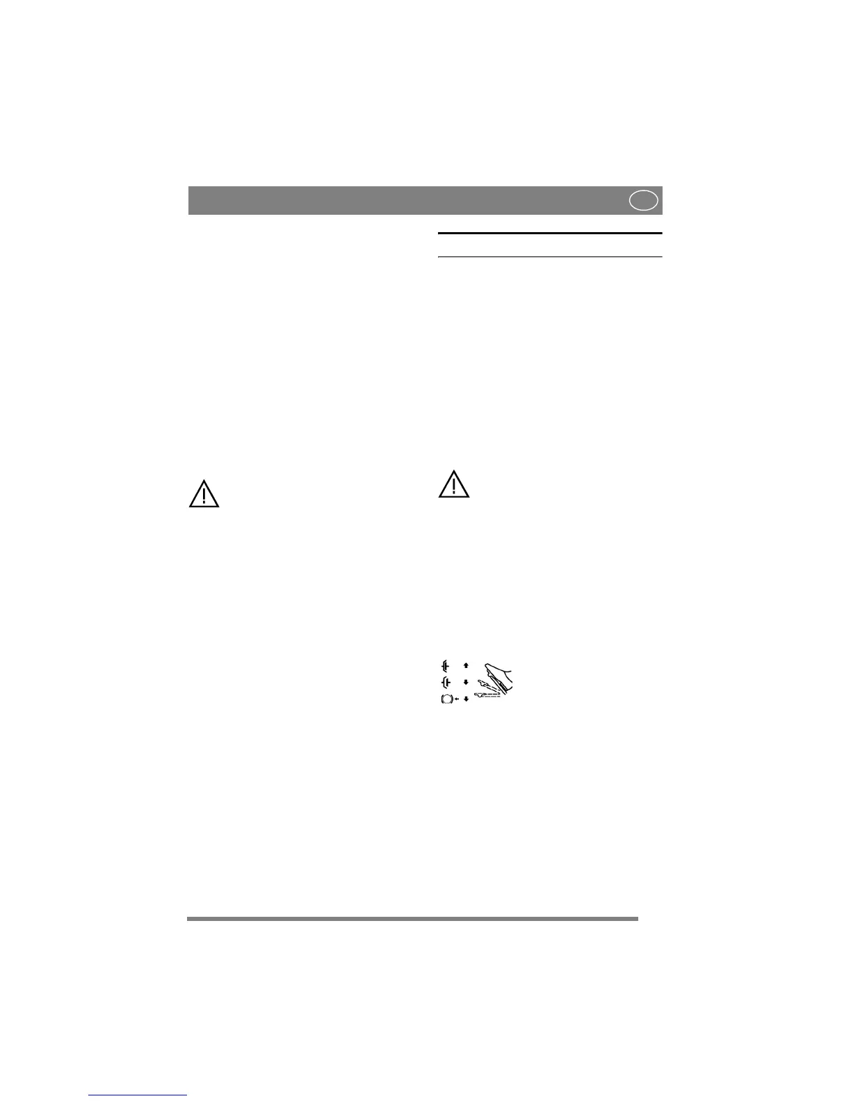
4.4.2 SERVICE BRAKE/CLUTCH (6:M)
(2105M)
A pedal that combines both service brake and
clutch. There are 3 positions:
1. Pedal released – forward drive
engaged. The machine will
move if a gear is engaged.
Service brake not activated.
2. Pedal depressed halfway –
forward drive disengaged, gear
shifting can be performed.
Service brake not activated.
3. Pedal fully depressed –
forward drive disengaged.
Service brake fully activated.
NOTE! You must never regulate the operating
speed by slipping the clutch. Use a suitable gear
instead, so that the right speed is obtained.