10
ENGLISH
GB
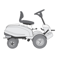
CONTROLS AND
INSTRUMENTS
Items 1 - 9, see figures 8 - 10.
1. IMPLEMENT LIFTER
A pedal for raising a front-mounted implement to
the transport position.
To lift up the implement, press the pedal down as
far as it will go. Then release the pedal, the imple-
ment lifter is now locked in the raised position.
To lower the implement, press the pedal down so
that the lock is released. Lower the implement lift-
er to the working position by slowly lifting your
foot from the pedal.
2A. SERVICE BRAKE/CLUTCH
(2105M)
A pedal that combines both service brake and
clutch. There are 3 positions:
1. Pedal released – forward drive
engaged. The machine will
move if a gear is engaged. Serv-
ice brake not activated.
2. Pedal depressed halfway –
forward drive disengaged, gear
shifting can be performed. Serv-
ice brake not activated.
3. Pedal fully depressed – for-
ward drive disengaged. Service
brake fully activated.
NOTE! You must never regulate the operating
speed by slipping the clutch. Use a suitable gear in-
stead, so that the right speed is obtained.
2B. SERVICE BRAKE (2125H)
A pedal that acts on the machine’s braking system.
There are 3 positions:
1. Pedal released – service brake
not activated.
2. Pedal depressed halfway –
forward drive disengaged. Serv-
ice brake not activated.
3. Pedal fully depressed – for-
ward drive disengaged. Service
brake fully activated.
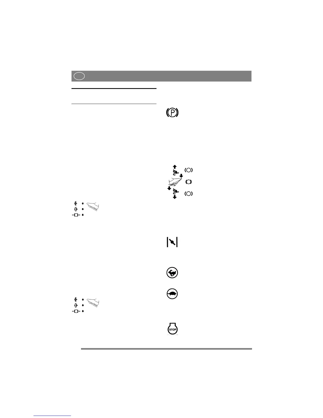
3. PARKING BRAKE
An inhibitor that can lock the brake pedal in the de-
pressed position.
Depress the brake pedal fully. Raise the
inhibitor and then release the brake pedal.
The parking brake is released by pressing
the brake pedal. The spring-loaded inhibitor slides
to one side.
Make sure that the parking brake is released when
operating the machine.
4. DRIVE PEDAL (2125H)
A pedal that activates the variable transmission.
1. Depress the pedal with the
ball of your foot – the machine
moves forwards.
2. No load on the pedal – the ma-
chine is stationary.
3. Depress the pedal with your
heel – the machine reverses.
The drive pedal regulates the speed. The more
pressure applied, the faster the machine will move.
5. THROTTLE/CHOKE CONTROL
A control for setting the engine speed and to choke
the engine when starting from cold.
1. Choke – for starting a cold engine. The
choke is located in the top of the groove.
Avoid operating the machine in this posi-
tion, taking care to move the control to full
throttle (see below) when the engine is
warm.
2. Full throttle – when the machine is in
operation, full throttle should always be
used.
3. Idling.
6. IGNITION LOCK
Ignition lock used for starting/stopping the engine.
Four positions:
1. Stop position – the engine is short-
circuited. The key can be removed.