- 4 -
NE-4120-ST:
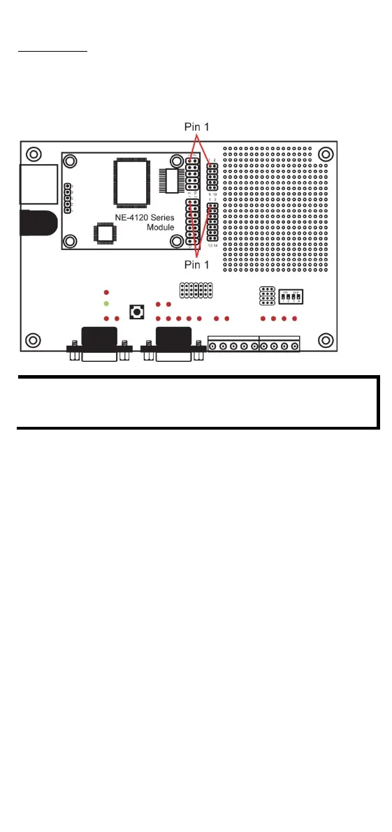
The module and evaluation board have two jumper arrays, each with a
pin labeled 1. Be sure to connect the correct Pin 1 on the module to the
correct Pin 1 on the evaluation board.
NE-4120-ST Starter Kit
For detailed information about the pin assignments, wiring, LED
indicators, and board layouts, refer to Chapter 2 of the NE
-
4100 Series User’s Manual.
Connect the 12 VDC power line with the evaluation board’s
power jack.
Use an RJ45 Ethernet cable to connect the NE evaluation
board plus module to an Ethernet network. Note that for NE
-
-
4120, the RJ45 Ethernet port is located on the
evaluation board. For NE
-4110, the RJ45 Ethernet port is
odule itself.
Use the serial data cable to connect the evaluation board to a
serial device.
For NE-4110-ST and NE-4120-ST, use jumper JP2 on the
evaluation board to select the proper serial interface. See
pages 3
-6 and 3-7 of the NE-4100 Series User’s Manual for

 Loading...