— 1 — — 2 — — 3 —
NPort 4511 Quick Installation Guide
First Edition, September 2004
1. Overview
NPort 4511 is a professional Programmable Communication Gateway
that makes your RS-232/422/485 devices network-ready. Its
programmable nature makes it a value-added developing platform that
is suitable for protocol conversion applications. NPort 4511 is a
flexible, reliable, cost-effective, and customizable solution that gives
System Integrators greater design flexibility.
2. Package Checklist for NPort 4511-ST
NPort 4511-ST is a convenient Starter Kit that can be used to evaluate
NPort 4511. The NPort 4511-ST package contains the following items:
! 1 NPort 4511 unit
! Documentation and Software CD
Contains Auto-Run Installation Shield, Software Development
Kit (SDK) and library, User’s Manuals, and Turbo-C
Installation Package.
! Accessories
Switching Power Adaptor, Ethernet Cross-Over Cable,
CBL-F9M9-150, Mini Adaptor, RS-232 Loopback Tester,
Wiring Terminal, and DIN-Rail Mounting Kit
! Miscellaneous
Turbo-C License Card, Moxa 5-year Warranty Booklet
NOTE: Notify your sales representative if any of the above items is
missing or damaged.
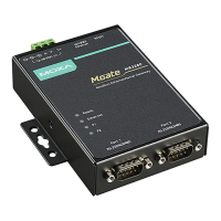
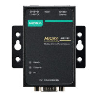
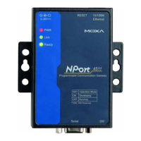
3. Hardware Introduction
As shown in the following figures, NPort 4511 has one 3-in-1 serial
port, that supports RS-232/422/485 serial interfaces.
Female DB9 serial port
Front Panel View
DIP Switches
ON
123
RJ45 10/100BaseTx Ethernet port
Reset button
Power input
Rear Panel View
DIN-Rail screw holes
Wall Mount screw holes
Top Panel View
Serial
RESET
10/100M
Ethernet
PWR
Link
Ready
Programmable Communication Gateway
4511
SW1 Operation Mode
ON Developing
OFF Running
* SW2, SW3 Reserved
SW
12-30V
Reset Button—Press the Reset button continuously for 5 sec to load
factory defaults: Use a pointed object, such as a straightened paper clip
or toothpick, to press the reset button. This will cause the Ready LED
to blink on and off. The factory defaults will be loaded once the Ready
LED stops blinking (after about 5 seconds). At this point, you should
release the reset button.
LED Indicators—The top panels of NPort 4511 have three LED
indicators, as described in the following table.
LED
Name
LED
Color
LED Function
red Power in on.
PWR
off Power is off, or power error condition exists.
orange
10 Mbps Ethernet connection.
green
100 Mbps Ethernet connection.
Link
off Ethernet cable is disconnected, or has a short.
green NPort 4511 system is ready.
Ready
off NPort 4511 has malfunctioned (if PWR LED is on)
DIP Switch Settings—The top panel of NPort 4511 contains the
selection table for DIP switch 1 (SW1), which is used to select NPort
4511’s operation mode. The DIP switch SW1 is located on NPort
4511’s front panel.
123
ON
SW1 Operation Mode
ON Developing
OFF Running
Keep the following points in mind when setting the DIP switches.
! DIP Switch SW1 selects NPort 4511’s Operation Mode.
! DIP Switches SW2 and SW3 are not functional.
4. Software Installation Information
To begin with, you will need to install the SDK utility, library, and
Turbo C compiler on the host computer.
1. Insert the Documentation and Software CD into the computer’s
CD-ROM drive.
2. Once the Moxa NPort 4511 SDK and Document CD window is
launched, click the Install SDK button and then follow the instruction
on the screen.
3. To install Turbo C, return to the Moxa NPort 4511 Documentation
and Software CD window and then click the INSTALL Turbo C
button.
5. Hardware Installation Information
Take the following steps to connect NPort 4511’s power adapter.
1. Plug the power adapter’s DC plug into NPort 4511’s DC-IN jack.
2. Plug the power adapter into an electrical outlet.
Set up a development environment as follows,
1. Connect NPort 4511 to a host via an Ethernet network.
2. Connect NPort 4511 to a target device via serial port.
6. Serial Port Pin Assignments
Female DB9
5 4 3 2 1
9 8 7 6
Pin RS-232 RS-422
RS-485
(2-wire)
1 DCD RxD-(A) ---
2 TxD RxD+(B) ---
3 RxD TxD+(B) Data+(B)
4 DSR TxD-(A) Data-(A)
5 GND GND GND
6 DTR CTS-(A) ---
7 CTS CTS+(B) ---
8 RTS RTS+(B) ---
9 --- RTS-(A)
P/N: 18020451130