EasyManua.ls Logo

MPC SP-502 - User Manual

MPC SP-502
5 pages
Print Icon
To Next Page IconTo Next Page
Loading...
1 | P a g e
TIP SHEET
Installation Tips for your SP-502/SP-402 + KEY-OVERRIDE-ALL (4) + SPDT T1649 v1.3 3/5/14
(for Toyota/Lexus Vehicles)
Thank you for purchasing your remote start from MyPushcart.com - an industry leader in providing remote starts to do-
it-yourself installers since 1999. We’ve put this tip sheet together to help you with your installation. The purpose of
this sheet is to help you organize your installation - not to replace your installation manual. You will still need to refer to
that.
If you provided us with your vehicle model/year at the time of purchase, you will have a wiring chart for your particular
vehicle. We’re going to refer to that a lot. If you do not have the wiring chart, email us at sales@mypushcart.com so
we can send you a copy. Be sure to include the model/year of your vehicle, your name and your sales order number.
Two very important things before you get started:
Read the entire installation manual. There are several safety tips in there that you need to know before you
start
Avoid using a test light to probe wires. Test lights can set off air bags if you probe the wrong wire. Your
vehicle wiring chart will identify the correct wires that you’ll be tapping on to in your car. If you must probe,
use a digital multi-meter. They’re inexpensive and won’t set off air bags.
Overview
There are 4 basic steps to this remote start installation. We’re going to address each of these:
1. Wiring
2. programming
3. Test
4. Button it up!
When you open up your remote start, you’re going to see a whole bunch of wires. You’re not going to use all of them.
The remote starts are designed with wiring options for a variety of cars and no car is going to use all of them. We’re
going to break the wiring down into only the needed wires you need from the remote starter. Here’s where the vehicle
wiring chart comes into play. The wiring chart will help you locate the wires that you’re going to need in your car.
Don’t be intimidated by all the different wires listed on the chart – you’re only going to be using a few of them.
Reading your wiring chart
Each line of the wiring chart contains 3 pieces of information that you will need:
The “Circuit” or “Wire/Function”
The color of the wire in the car
The location of the wire in the car
See Installer’s Tip # 2 for tips on how to make your wiring connections
Step 1 - Making your remote start wiring connections:
The following table shows you where to connect the wires from your remote start into the car. Any wires on your
remote start that are NOT listed in the table are NOT USED. In most cases, the wires on the remote start are way longer
than needed. Trim off excess wire when you make your connections, but leave some slack - this will allow you a little
flexibility when it comes time to stow the remote start module after the installation is completed.
Question and Answer IconNeed help?

Do you have a question about the MPC SP-502 and is the answer not in the manual?

Summary

Remote Start Installation Overview

Key Installation Steps

Outlines the four main phases: wiring, programming, testing, and finalization.

Understanding Wiring Charts

Explains how to interpret the vehicle wiring chart for successful connections.

Step 1: Vehicle Wiring Connections

SP402;502 Wiring Harness Guide

Details connections for the SP-402/502 wiring harness and notes on parking lights.

Hood Pin Switch Safety Feature

Explains the purpose and connection of the hood pin switch.

Step 2: Bypass Module Wiring

KEY-OVERRIDE-ALL Bypass Connections

Details the required connections for the KEY-OVERRIDE-ALL bypass module.

Steps 3 & 4: Programming and Testing

Programming the Bypass Module

Provides instructions for programming the bypass module using the remote.

System Testing and Finalization

Covers testing door locks, trunk release, remote start, and tidying wiring.

Installers Tips

Module and Component Placement

Guidance on selecting locations for the remote start module and other components.

Wiring Connection Methods

Describes three methods for making secure wire connections: solder, wrap, and T-taps.

Overview

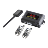
This document provides installation tips for the SP-502/SP-402 remote start system, including the KEY-OVERRIDE-ALL (4) and SPDT components, specifically for Toyota/Lexus vehicles. It serves as a guide for do-it-yourself installers, complementing the main installation manual.

Function Description:

The SP-502/SP-402 is a remote start system designed to allow users to start their vehicle remotely. It integrates with the vehicle's existing electrical system to control ignition, starter, accessory, and parking lights. Keyless entry features, such as door lock and unlock, and trunk/hatch release, are also supported. The system includes a bypass module (KEY-OVERRIDE-ALL) to interface with the vehicle's immobilizer (PATS) system, allowing the remote start to function without a physical key in the ignition. A hood pin switch is included as a safety feature to prevent remote starting when the hood is open.

Important Technical Specifications:

  • Model Compatibility: SP-502/SP-402 with KEY-OVERRIDE-ALL (4) and SPDT.
  • Vehicle Compatibility: Toyota/Lexus vehicles (specific models/years determined by wiring chart).
  • Power Input: Constant 12V (+) via RED x2 wires on the 6-PIN HARNESS.
  • Ignition/Starter/Accessory: Connections for Ignition, Ignition #2 (if present), Starter, and Accessory circuits.
  • Parking Lights: Supports both positive (+) and negative (-) polarity parking light circuits. The RED/BLACK wire on the 12-PIN HARNESS selects polarity (connect to +12V for positive, ground for negative), and the WHITE wire is the actual parking light output.
  • Ground: System ground connects to a solid metal point in the vehicle.
  • Safety Features:
    • Hood Pin Switch: Connects to the GRAY wire on the 12-PIN HARNESS. Prevents remote start activation when the hood is open.
    • Brake Switch: Connects to the WHITE wire on the 7-pin harness. Used to stop the engine after remote start.
  • Key Override/Bypass Module (KEY-OVERRIDE-ALL):
    • Connection Type: Connects to the BLUE wire on the 4-pin harness of the remote start.
    • Bypass Module Connections:
      • Blue wire: Connects to the orange ground-when-running wire in the remote start's 12-pin harness.
      • Green wire: Connects to the vehicle's key sense wire (typically near the ignition barrel).
      • Purple/White (RX Data IN) and Yellow/Black (TX Data OUT) wires: Connect to the RX and TX wires on the vehicle's PATS connector (located on the steering column).
    • Programming: Requires a specific sequence involving the programming button, inserting connectors, and using a functional key in the ignition (or starting the vehicle with the key for 80-bit G-key systems).
  • Optional Features:
    • Trunk/Hatch Release: Connects to the GREEN/RED wire on the 12-PIN HARNESS (may require a relay for (+) or (+/-) types).
    • Vehicle OEM Alarm Disarm: ORANGE/BLACK wire on the 12-pin harness. Only used if the factory alarm is triggered by remote start.
    • Second Starter Wire: If the vehicle has a second starter wire, a relay (included in the kit) is used to energize it with a positive signal.

Usage Features:

  • Remote Start Activation: Pressing the "start" button on the remote.
  • Engine Stop: Stepping on the brake pedal.
  • Door Lock/Unlock: Pressing 'lock' and 'unlock' buttons on the remote.
  • Trunk/Hatch Release: Pressing and holding the 'trunk' button for 3 seconds (if connected).
  • Programming Button: Used for programming the bypass module.
  • Status LED: Provides visual feedback during programming and operation.

Maintenance Features:

  • Wiring Connections: Emphasizes solid and secure "tap on" connections. Three methods are described:
    1. Solder and Tape: Preferred by professionals for reliability. Involves stripping insulation, tinning the car wire, wrapping the remote start wire, soldering, and taping.
    2. Wrap and Tape: Popular and reliable. Involves stripping insulation, separating car wire strands, passing the remote start wire through, wrapping it around both sides, and taping. A wire tie can prevent tape unraveling.
    3. "T-Taps": Plastic clips squeezed onto car wires, with the remote start wire inserted and crimped. Different sizes for different gauge wires (yellow for larger, red for smaller). Taping and wire tying are recommended to prevent opening. A "tap kit" with taps and insulated male spade connectors is available.
  • Wire Management: After installation and testing, all wiring should be neatly bundled with zip ties or electrical tape.
  • Module Placement: The remote start module and bypass module should be stowed in a secure location under the dash on the driver's side, away from moving parts like pedals, e-brake, and steering column.
  • Antenna Placement: If equipped, mounts to the windshield in a top corner or behind the rearview mirror.
  • Programming Button Placement: Requires a ¼" hole. Typically installed in the driver's kick panel, center console, or underside of the dash.
  • Status LED Placement: Requires a ¼" hole. Placed in a visible spot on the dash with clearance and within wire reach.
  • Hood Pin Switch Placement: Requires a 3/8" hole. Installed in the engine compartment where the closed hood will depress the plunger.

The document stresses the importance of reading the entire installation manual for safety tips and avoiding test lights (using a digital multi-meter instead) to prevent accidental airbag deployment. It also highlights the necessity of a vehicle-specific wiring chart for identifying correct wires and locations.

MPC SP-502 Specifications

General IconGeneral
BrandMPC
ModelSP-502
CategoryRemote Starter
LanguageEnglish