09 10
Step 4: wire
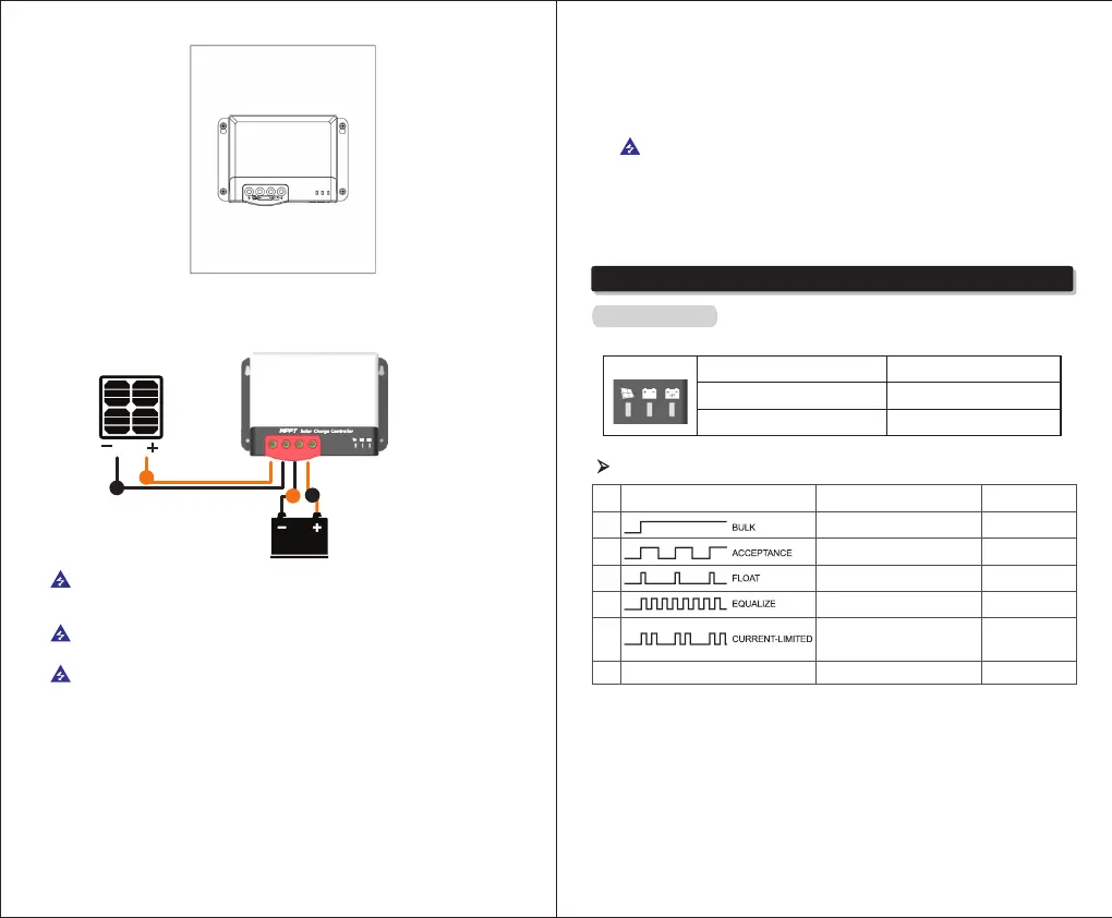
For installation safety, we recommend a wiring sequence as follows; however, wiring in other sequence
instead of this one will not damage the controller.
When all wires are connected firmly and reliably, check whether the wiring is proper and
whether the polarity is reversed. After confirmation, connect the battery fuse or circuit breaker and
observe whether the LED indicator is on. If not, disconnect the fuse or circuit breaker immediately
and check whether wiring is correct.
As the battery is properly energized, connect the solar panel. If there is sufficient sunlight, the
charge indicator of controller will be steady on or flash and start to charge the battery.
Note:
1) Note that the battery fuse shall be installed as close as possible to the battery terminal. The
recommended distance is not more than 150mm.
2) The battery temperature is 25°C (fixed value) when the controller is not collected to a
remote temperature sensor.
2
1
3
4
Warning: Danger, Electric shock hazards! We strongly recommend connect a fuse or circuit
breaker to the PV array and battery terminals to prevent electric shock hazards during wiring or
error operation, and make sure that fuse or circuit breaker is disconnected before wiring.
Warning: Danger, High voltage hazards! Photovoltaic arrays may generate very high open
circuit voltages. Disconnect circuit breaker or fuse before wiring and be very careful during wiring.
Warning: Danger, Explosion hazards! If the positive and negative terminals of battery and the
wires connected to them are short-circuited, it may cause a fire or explosion. Please be very careful
in operation.
Please connect the battery first, and then the solar panel. Please follow the “+” first and “-”
next method when wiring.
Warning: When the controller has stopped charging for 10 minutes, reverse polarity of the
battery can damage the controller's internal components.
3. Product Operation and Display
3.1 LED Indicators
① ② ③
①---PV array indication
②---BAT indication
③---BAT Type indication
Indicate the current charging mode
of controller
Indicate the current state of battery.
Indicate the current battery type.
①
②
③
④
⑤
⑥
PV array indicator:
Steady on
Slow flashing
(On:1s, off: 1s, cycle: 2s)
Single flashing
(On:0.1s, off: 1.9s, cycle: 2s)
Quick flashing
(On:0.1s, off: 0.1s, cycle: 0.2s)
Double flashing
(On:0.1s, off: 0.1s, then, On:0.1s, off: 1.7s, cycle: 0.2s)
Off
MPPT charging
Boost charging
Floating charging
Equalizing charging
Current-limited
charging
No charging
No.
Indicator state
Charging state
CHARGE STATUS
There are a total of three indicators on the controller