mr
.
steam
®
steamtherapy
®
Installation, Operation & Maintenance Manual
_____________________________________________________________________
installer
4
LOCATING THE STEAM GENERATOR UNIT
S
elect a location as near as practical to the steam room. Typical locations include: closet, vanity cabinet, heated attic or basement.
NOTE:
THE STANDARD LENGTH OF THE CABLE FOR CONNECTING THE CONTROL TO THE STEAM GENERATOR IS 30 FEET. THE
STEAM GENERATOR AND CONTROL MUST BE LOCATED ACCORDINGLY. A 60 FOOT CABLE (PN 103990-60) IS AVAILABLE AS A
SPECIAL ORDER PART.
(I
TEMS 1-7)
1.
DO NOT install steambath generator or plumbing lines in
unheated attic or any locations where water could freeze.
2.
DO NOT install steambath generator inside steam room.
3.
DO NOT install steambath generator outdoors or wherever
environmental conditions may affect the safety and/or
performance of the generator.
4.
DO NOT install steambath generator near flammable or corro-
sive materials or chemicals such as gasoline, paint thinners,
or the like. Installation in areas having high concentrations of
chlorine (such as pool equipment room) must be avoided.
5.
Install steambath generator on a solid and level surface.
Keyhole slots are provided for wall mounting. Insure the
steam generator is properly secured and level when mounting
with keyhole slots.
6.
Install steambath generator in an upright position only.
7.
Steam line, safety valve, drain valve, plumbing and steamheads
become hot during operation and remain hot after shutdown
for a period of time. Provide appropriate protection, including
insulating plumbing lines. Avoid plumbing runs and steamhead
locations that can come in contact with bathers.
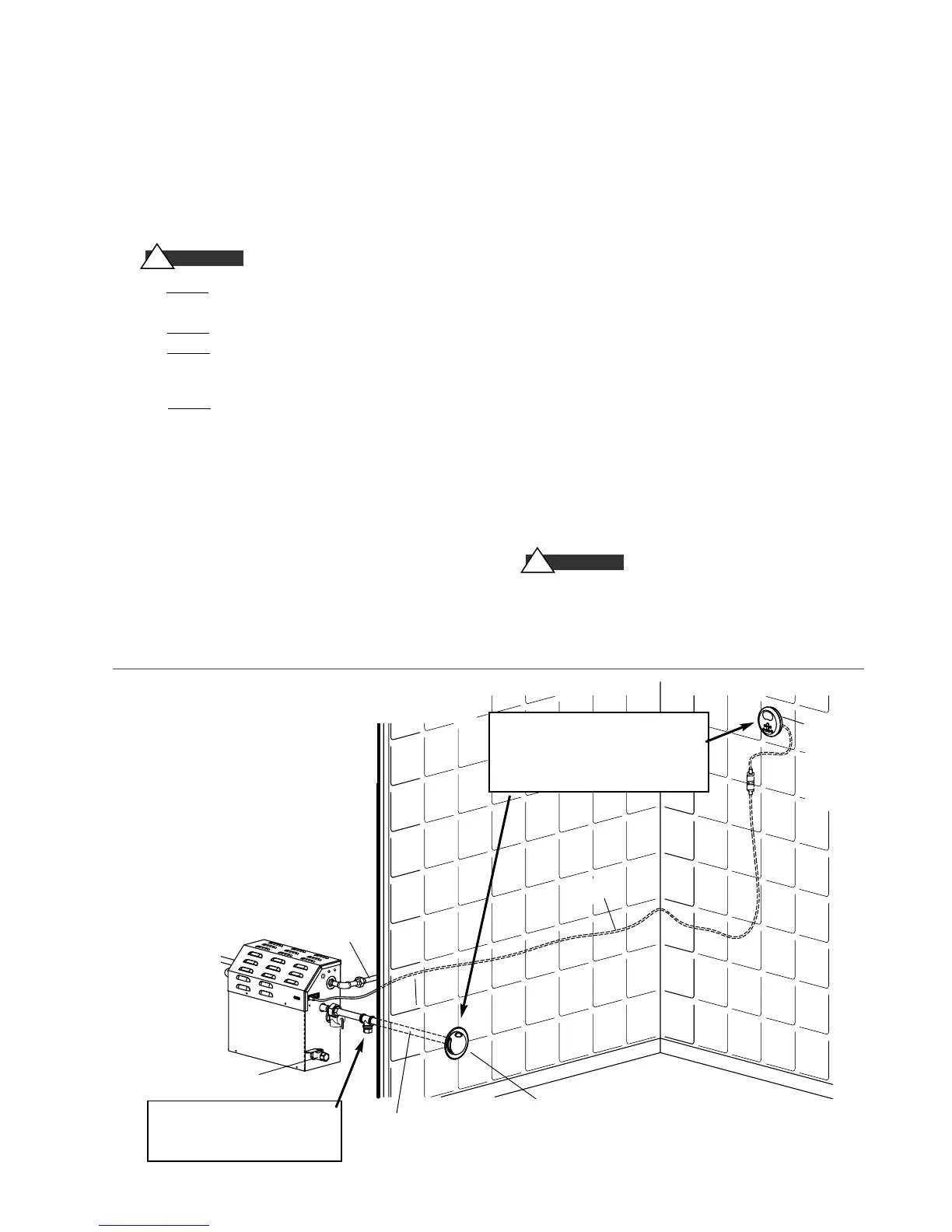
NOTE: FOR ILLUSTRATIVE PURPOSES ONLY.
Consult with qualified designer, architect or
contractor for steam room construction details.
Provide unions as required to facilitate
installation and disconnect of piping
Steam
Generator
Field installed
power supply
Field installed
steam supply pipe
Drain Valve should be closed
when AutoFlush is not installed
Control
cable
Steam Head (shown with optional acrylic shield)
See page 7 for Steam Head Installation information
eTEMPO
®
or
eTEMPO/PLUS
®
Control
See page 17-22
for installation
information.
Field installed
water supply line
IMPORTANT:
The control features an inte-
gral temperature sensor. Locate the control in a
location representative of the desired steambat-
hing temperatures. Do not locate the control above
or near the steam head or direct steam emissions.
TYPICAL MR.STEAM INSTALLATION
!
WARNING
IMPORTANT: (I
TEMS 8-11)
8.
Install anti-water hammer device as necessary.
9
.
Provide a minimum of (12) inches at both ends and
top of the steam generator or as required for servicing.
See page 8.
10.
Provide unions as required to facilitate installation
and disconnection of piping.
11
.
Mr.Steam controls can be located inside the steam
room or on the outside of the steam room.
See CONTROL INSTALLATION section (pgs. 17-22) for
specific details. If the controls are located outside
the steam room, a remote sensor (PN MSTS) is
required (see pgs. 21-22).
NOTE:
Mr.Steam Generators (inclusive of the eTempo
series Controls) are CE and UL listed.
The MS series of steam generators
are for residential use only. Commercial or other non-
residential applications void the warranty and may
adversely affect product performance. Use only
Mr.Steam eTempo
®
series controls.
!
WARNING
When installing the optional AromaSteam™,
install a downward facing 90-degree T in the
steam supply line. See the AromaSteam™
Installation Manual for complete information.
 Loading...