EasyManua.ls Logo

mr. steam MS90E - User Manual

Default Icon
2 pages
Print Icon
To Next Page IconTo Next Page
Loading...
Instructions for MS, MX, CT & SAH
Generator PC Board Replacement
mr
.
steam
®
For MrSteam Models MS90E, MS150E, MS225E, MS400E, MSSUPER1E, MSSUPER2E, MSSUPER3E,
MX4E, MX5E, MX6E, CT6E, CT9E, CT12E, CT15E, SAH3000, SAH4500, and SAH6000
1. MS, MX, CT & SAH Generator PC Board Replacement only to be performed after consultation with a MrSteam
Technical Service Representative.
2. REPAIR PROCEDURES MUST BE ACCOMPLISHED BY A QUALIFIED LICENSED ELECTRICIAN.
3. Use only MrSteam supplied replacement parts.
4. Follow all instructions in the Steam Generator Installation, Operation, and Maintenance Manual. This manual is
provided with the generator and is also available online at: www.mrsteam.com/technical.
GENERATORS WITH EXPRESS STEAM AND MAX GENERATORS REQUIRE JUMPER
ADJUSTMENT. FAILURE TO ADJUST JUMPERS MAY RESULT IN EQUIPMENT DAMAGE.
IMPORTANT NOTE:
As you follow these instructions, you will notice warning and caution symbols. This blocked information is
i
mportant for the safe and efficient installation and operation of this Generator. These are types of potential hazards that may occur
during this installation and operation:
states a hazard may cause serious injury or death if precautions are not followed.
signals a situation where minor injury or product damage may occur if you do not follow instructions.
IMPORTANT NOTE:
This highlights information that is especially relevant to a problem-free installation.
BE CERTAIN ELECTRICITY IS SHUT OFF AT MAIN PANEL BEFORE ATTEMPTING TO WIRE OR SERVICE THE PC BOARD.
WARNING
!
WARNING
!
C
AUTION
!
CAUTION
!
PC Board Replacement
1. Turn off breaker to the steam
generator.
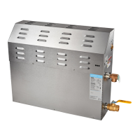
2. Unplug all connections to the
right side of the generator,
see figure 1.
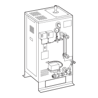
3. Unscrew 2 screws on top cover
and remove top cover to the
generator, see figure 2.
Steam
Generator
Figure 1
Steam
Generator
Screws
Top Cover
Figure 2
1 2 3 4 5 6 7 8
Position 2
Position 1
Position 2
Position 1
1 2 3 4 5 6 7 8
Position 2
Position 1
1 2 3 4 5 6 7 8
Default Jumper Express Steam Jumper Location MX Generator Jumper Location
Location Move Jumper 4 to Position 1 Move Jumper 6 to Position 1
All manuals and user guides at all-guides.com

Questions and Answers

Overview

This document provides instructions for replacing the PC board in MrSteam MS, MX, CT, and SAH series steam generators. It is a technical guide intended for qualified personnel, emphasizing safety and proper procedure.

Function Description

The document outlines the steps for replacing the main Printed Circuit Board (PC Board) in various MrSteam generator models. This board is the central control unit for the steam generator, managing its operation, accessories, and safety features. The replacement procedure ensures the continued proper functioning of the steam generator.

Important Technical Specifications

The instructions apply to a wide range of MrSteam generator models, including:

  • MS Series: MS90E, MS150E, MS225E, MS400E, MSSUPER1E, MSSUPER2E, MSSUPER3E
  • MX Series: MX4E, MX5E, MX6E
  • CT Series: CT6E, CT9E, CT12E, CT15E
  • SAH Series: SAH3000, SAH4500, SAH6000

The document highlights specific jumper settings required for generators equipped with Express Steam and MX models. For Express Steam, Jumper 4 must be moved to Position 1. For MX generators, Jumper 6 must be moved to Position 1. Failure to adjust these jumpers can result in equipment damage. The PC board interfaces with various components via a 6-wire cable assembly, green and purple wires (for GND and WLS terminals), and connections for control panels and other accessories.

Usage Features

The primary usage feature described is the PC board replacement itself, which is a maintenance task rather than a user operation. However, the document touches upon aspects that relate to the generator's operation:

  • Test Button: The PC board includes a "Test Button" which, when pressed, allows the generator to run for 10 minutes. Pressing it again turns the generator off. This feature is crucial for verifying the functionality of the newly installed PC board.
  • Accessory Integration: The PC board supports integration with various accessories, indicated by the need to unplug and then re-plug all accessories connected to the board during replacement. This suggests the board manages the functions of components like the "Steam Genie" and "AutoFlush" systems, which are visible in the diagrams.
  • Control Panel Connection: The control panel connects to the right side of the generator, indicating that the PC board facilitates communication and control from the user interface.

Maintenance Features

The document is essentially a maintenance guide, detailing the steps for PC board replacement:

  • Safety First: Emphasizes the critical importance of shutting off electricity at the main panel before any wiring or servicing. This is a fundamental safety precaution for electrical maintenance.
  • Qualified Personnel: States that PC board replacement should only be performed after consultation with a MrSteam Technical Service Representative and must be accomplished by a qualified licensed electrician. This ensures the procedure is carried out correctly and safely.
  • Genuine Parts: Mandates the use of only MrSteam-supplied replacement parts, ensuring compatibility and optimal performance.
  • Documentation Reference: Directs users to follow all instructions in the Steam Generator Installation, Operation, and Maintenance Manual, available online, for comprehensive guidance.
  • Step-by-Step Procedure: Provides a clear, numbered sequence of steps for replacement:
    1. Turn off the breaker to the steam generator.
    2. Unplug all connections from the right side of the generator.
    3. Remove the top cover of the generator by unscrewing two screws.
    4. Unplug the 6-wire cable assembly from the PC board.
    5. Unplug the green and purple wires from the PC board.
    6. Unplug all accessories connected to the PC board.
    7. Remove the old PC board by using a flat-head screwdriver to push in triangular locking tabs on white plastic standoffs while pushing the board up.
    8. Fasten the new PC board to the 8 white plastic standoffs.
    9. Plug the green wire to the GND terminal and the purple wire to the WLS terminal on the PC board.
    10. Plug in the 6-wire cable assembly to the PC board.
    11. Plug in the control to the right side of the generator.
    12. Plug in all previously disconnected accessories.
    13. Turn on the breaker box.
    14. Press the Test Button on the PC board to run the generator for 10 minutes.
    15. Press the Test Button again to turn off the generator.
    16. Replace the generator's top cover and fasten the two screws.
  • Visual Aids: Includes figures (Figure 1, Figure 2, Figure 3, Figure 4, Figure 5) to visually guide the user through the process, showing connection points, component locations, and the method for removing the PC board. Figure 3 specifically illustrates wiring for different model series (MS 90E-MS 400E, MS Super 1E-3E and CT6E-15E, SAH3000, SAH4500, SAH6000, and MX 4E-6E), highlighting the consistency in PC board layout across these models.
  • Jumper Adjustment: Crucially, it warns about the need for jumper adjustments for Express Steam and MX generators to prevent equipment damage, indicating a specific configuration requirement for these models.
  • Warning and Caution Symbols: Uses "WARNING" and "CAUTION" symbols to highlight potential hazards, emphasizing safety during the procedure. "IMPORTANT NOTE" is used for information critical to a problem-free installation.

Overall, this document serves as a comprehensive, safety-conscious guide for the specific maintenance task of replacing a PC board in MrSteam generators, ensuring that the process is performed correctly and safely to restore the generator's functionality.

mr. steam MS90E Specifications

General IconGeneral
Brandmr. steam
ModelMS90E
CategoryPortable Generator
LanguageEnglish

Related product manuals