a. Turn the power on without clamping on to any wire.
b. Set
the rotary switch at 3
φ
4W
.
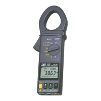
c.
Insert the test leads into the input ja
ck.
d. Connect the neutral line to the COM (black) terminal.
e. Connect the test probe
of the V (red) terminal to the first
phase (eg. R or L1).
f. Clamp on to the same phase (eg.
R or L1).
g.
The power clamp meter will
automatically select proper
range.
h. Wait unt
il the reading is
stable (about 3~6 seconds),
press the YELLOW button,
and W
L1
symbol will disappear.
and W
L2
symbol appears to instruct users to take
measurement of W
S(L2)
/PF
S(L2)
.
Second, measure W
S(L2)
/PF
S(L2)
(refer to figure 8)
a. Disconnect the test probe from the phase where jaws
is
clamp on in previous measurem
ent.
b. Connect the test probe of t
he V (red) terminal to the
second phase (eg. S or L2).
c.
Clamp the phase where test probe is connected to
(eg. S
or L2 phase)
d. The power clamp will automat
ically select proper range.
e. Wait
until the reading is stable (about
3~6 seconds),
press t
he YELLOW button, and W
L2
symbol will disappear.
W
L3
symbol will appear to instruct users to take
measurement of W
T(L3)
/PF
T(L3)
.
Third, measure W
T(L3)
/PF
T(L3)
(refer to figure 9)
a. Disconnect the test probe from the phase where ja
ws
clamped in previous measurem
ent.
b. Connect the test probe of the V (red) terminal to th
e third
phase (eg. T or L3 phase).
c.
Clamp the phase where test
probe is connected to (eg.
T or L3).
First, measure W
R(L1)
/PF
R(L1)
(refer to figure 7).
 Loading...