507769C05Page 42 of 55
5. Is the lter dirty or plugged? Dirty or plugged lters will
cause the limit control to shut the unit o.
6. Is gas turned on at the meter?
7. Is the manual main shut–o valve open?
8. Is the internal manual shut–o valve open?
9. Is the unit ignition system in lockout? If the unit locks
out again, inspect the unit for blockages.
Heating Sequence of Operation
1. When thermostat calls for heat, combustion air inducer
starts.
2. Combustion air pressure switch proves blower
operation. Switch is factory set and requires no
adjustment.
3. After a 15 second pre-purge, the hot surface ignitor
energizes.
4. After a 20 second ignitor warm-up period, the gas
valve solenoid opens. A 4-second “Trial for Ignition”
period begins.
5. Gas is ignited, ame sensor proves the ame, and the
combustion process continues.
6. If ame is not detected after rst ignition trial, the
ignition control will repeat steps 3 and 4 four more
times before locking out the gas valve. The ignition
control will then automatically repeat steps 1 through
6 after 60 minutes. To interrupt the 60 minute lockout
period, move thermostat from “Heat” to “OFF” then
back to “Heat”. Heating sequence then restarts at step
1.
Gas Pressure Adjustment
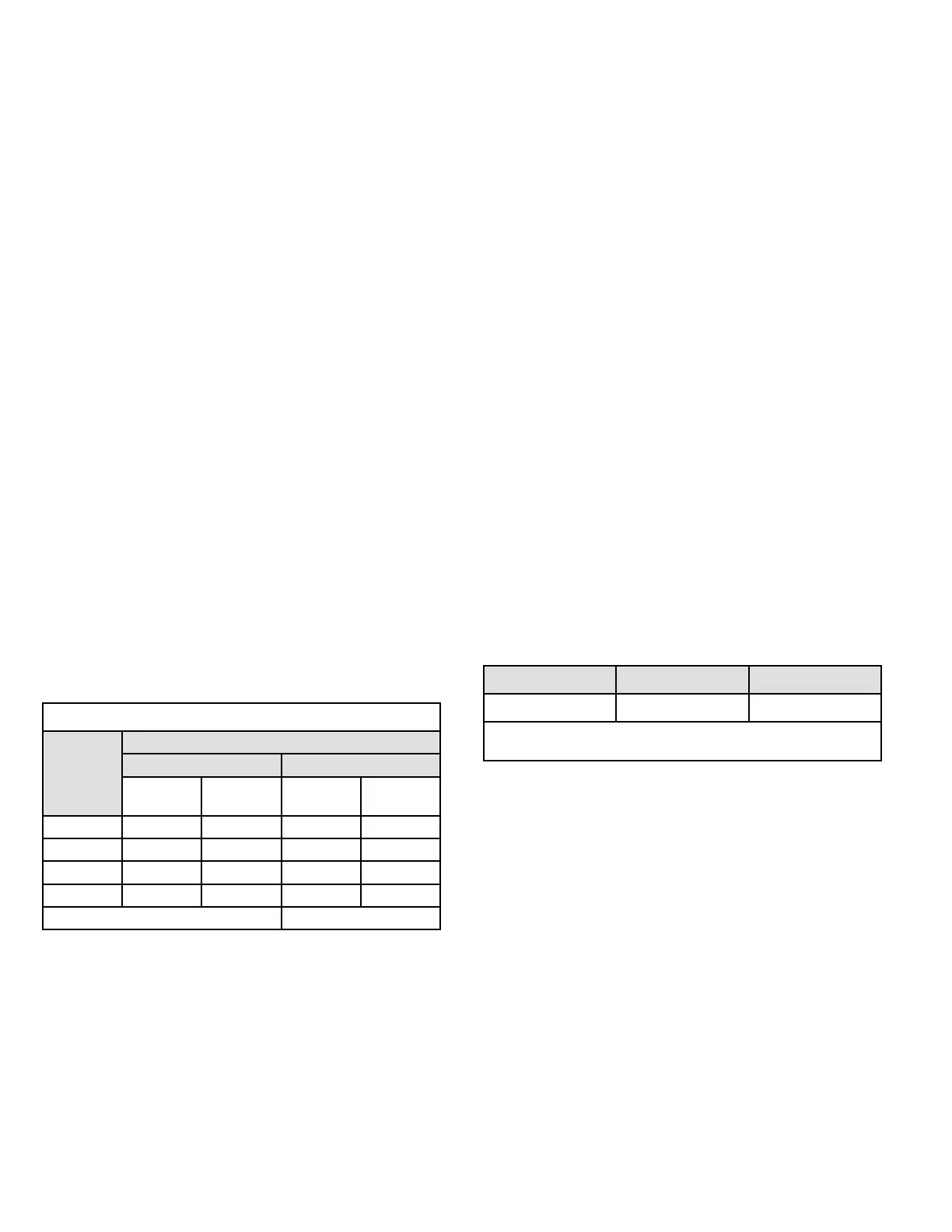
Gas Flow (Approximate)
Gas Meter Clocking Chart
Capacity
Seconds for One Revolution
Natural LP
1 cu ft
Dial
2 cu ft
Dial
1 cu ft
Dial
2 cu ft
Dial
-045 80 160 200 400
-070 55 110 136 272
-090 41 82 102 204
-110 33 66 82 164
Natural - 1000 btu/cu ft LP - 2500 btu/cu ft
Table 15.
NOTE: To obtain accurate reading, shut o all other gas
appliances connected to meter.
Furnace should operate at least 5 minutes before checking
gas ow. Determine time in seconds for two revolutions of
gas through the meter. (Two revolutions assures a more
accurate time.) Divide by two and compare to time in Table
15. If manifold pressure matches Table 17 and rate is
incorrect, check gas orices for proper size and restriction.
Remove temporary gas meter if installed.
Supply Pressure Measurement
A threaded plug on the inlet side of the gas valve provides
access to the supply pressure tap. Remove the threaded
plug, install a eld-provided barbed tting and connect a
manometer to measure supply pressure. Replace the
threaded plug after measurements have been taken.
Manifold Pressure Measurement
1. Remove the threaded plug from the outlet side of
the gas valve and install a eld provided barbed
tting. Connect to a manometer to measure manifold
pressure.
2. Start unit and allow 5 minutes for unit to reach steady
state.
3. While waiting for the unit to stabilize, observe the
ame. Flame should be stable and should not lift from
burner. Natural gas should burn blue.
4. After allowing unit to stabilize for 5 minutes, record
manifold pressure and compare to value given in
Table 17.
NOTE: Shut unit o and remove manometer as soon as an
accurate reading has been obtained. Take care to remove
barbed tting and replace threaded plug.
Proper Combustion
Furnace should operate minimum 15 minutes with correct
manifold pressure and gas ow rate before checking
combustion. Take combustion sample beyond the ue
outlet and compare to the tables below. The maximum
carbon monoxide reading should not exceed 100 ppm.
Table 16.
Unit CO
2
% for Nat CO
2
% for L.P.
All 7.2 - 8.2 8.6 - 9.6
The maximum carbon monoxide reading should not exceed
100 ppm.
High Altitude Information
NOTE: In Canada, certication for installations at
elevations over 4500 feet (1372 m) is the jurisdiction of
local authorities.
Units may be installed at altitudes up to 10,000 ft. above
sea level. See Table 17 for de-rate manifold values. Units
installed at altitude of 7501 - 10,000 feet require an orice
change. Units installed at altitudes of 4501 - 10,000 feet
(1373 to 3048 m) require a pressure switch change which
can be ordered separately. Table 18 and Table 19 list
conversion kit and pressure switch requirements at varying
altitudes.
The combustion air pressure switch is factory-set and
requires no adjustment.
 Loading...