C
Christy JamesJul 31, 2025
Why is the red light always on for MrCool Air Handlers?
- AAlbert CuevasJul 31, 2025
A constant red light indicates a failure of the evaporator temperature sensor (T2).
Why is the red light always on for MrCool Air Handlers?
A constant red light indicates a failure of the evaporator temperature sensor (T2).
Highlights the importance of safety symbols and warnings for proper unit operation and user safety.
Details unit dimensions (H, W, L) and refrigerant connection valve sizes for different models.
Specifies minimum clearances for air inlet, outlet, and service access around the outdoor unit.
Illustrates piping diagrams for cooling-only and cooling & heating systems across different models.
Provides circuit diagrams for cooling-only and cooling & heating configurations, including wire color codes.
Details electrical characteristics like frequency, phase, and voltage range for various unit models.
Defines acceptable room and outdoor temperature limits for cooling and heating operations.
A flowchart detailing the sequence of installation tasks from location selection to test operation.
Provides criteria for selecting an optimal location for the indoor unit.
Outlines considerations for choosing a suitable location for the outdoor unit.
Details location selection, service space requirements, and installation guidelines for the outdoor unit.
Specifies maximum pipe lengths, height drops, and sizing guidelines based on model capacity.
Details the steps for cutting, insulating, and connecting refrigerant pipes, including brazing precautions.
Explains the importance of vacuum drying and outlines procedures for ordinary and special methods.
Specifies the required vacuuming capability and precision for the vacuum pump.
Provides formulas to calculate the additional refrigerant charge based on liquid pipe diameter and length.
Emphasizes safety precautions during charging and methods for verifying the correct refrigerant charge.
Covers insulation procedures, material selection, and purpose for refrigerant pipes.
Details insulation requirements for drainage pipes to prevent condensation and leakage.
Outlines key electrical wiring practices, grounding, and protection requirements.
Provides tables for selecting appropriate wire gauges for power and signal lines based on unit model.
Lists essential checks to perform before initiating the test operation of the unit.
Specifies points to check for both indoor and outdoor units during cooling mode test operation.
Explains system status indicators, alarm codes, and fault descriptions for normal operation and system lock.
Provides diagnostic flowcharts for sensor faults, pressure alarms, and temperature protection issues.
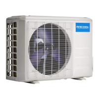
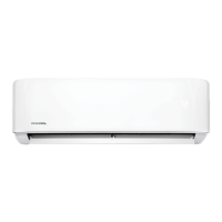
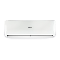
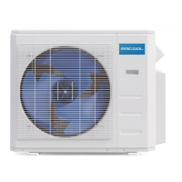
The MRCOOL PRODIRECT™ Series is a line of split-system heat pumps and air conditioners designed for residential and light commercial applications. These units are available in 1.5 to 5-ton capacities and boast a 13-14 SEER rating, indicating their energy efficiency. The series includes both heat pump models (HHP140*) and air conditioner models (HAC140*). The manual emphasizes that these instructions are intended for qualified and licensed service personnel to ensure proper installation, adjustment, and operation, warning that failure to follow them could lead to fire, electrical shock, property damage, personal injury, or death. The units are AHRI Certified® for Unitary Small AC and Unitary Small HP, ensuring they meet industry performance standards when the complete system is listed with AHRI.
The MRCOOL PRODIRECT™ Series units are designed to provide indoor climate control, offering both cooling and, for heat pump models, heating functionalities. They operate as split systems, meaning they consist of an outdoor unit (condenser/compressor) and an indoor unit (evaporator/air handler) connected by refrigerant piping and electrical wiring. The system circulates refrigerant to absorb heat from one area and release it into another, effectively cooling or heating the indoor space. The heat pump models can reverse this cycle to provide heating during colder months.
36,000 Btu/h: Max. Length 66 ft (20m), Max. Elevation 33 ft (10m), Max. Elbows 5.
| Brand | MrCool |
|---|---|
| Model | PRODIRECT Series |
| Category | Air Conditioner |
| Language | English |